Hi Shane and Brunswick, thanks...
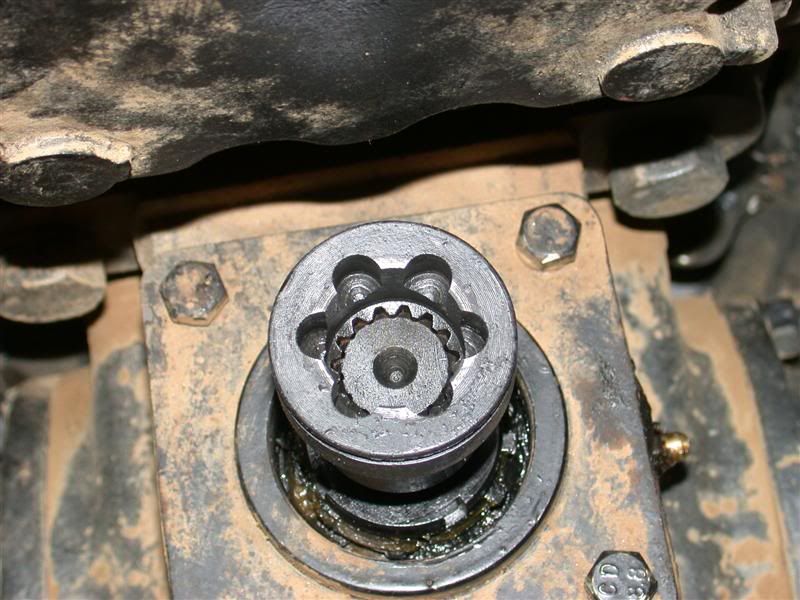
I made this repair because of the failure in that area.
I would be afraid to recommend to everyone to make the switch from the ball bearings to the dowels like I did because, even though it is working excellently, it is not OEM and for those who have dealers and warranties it might interfere by violating it.
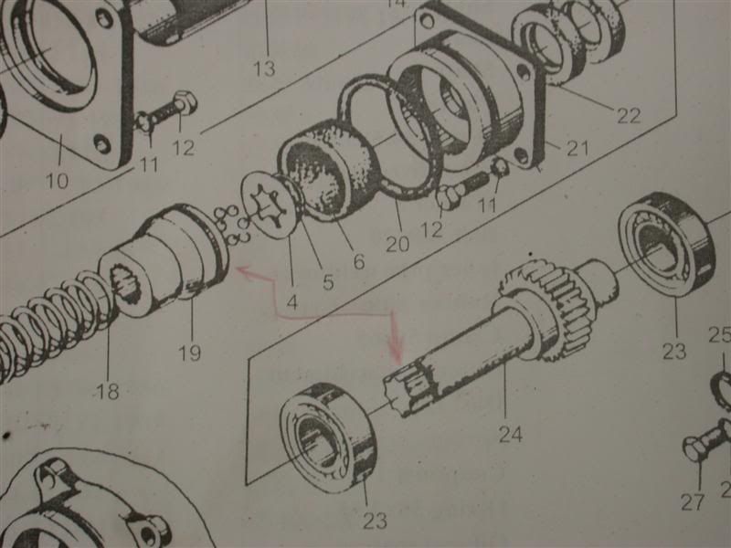
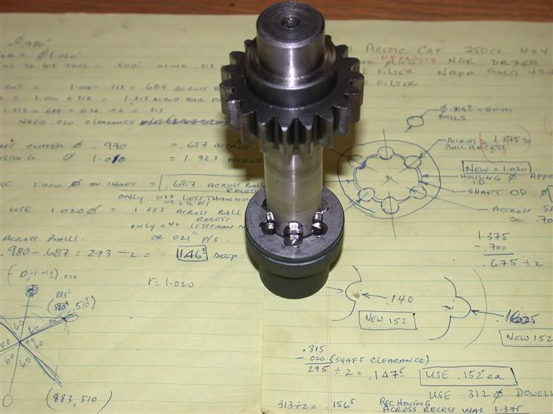
However, if you think about that connection and what the purpose of those OEM ball bearings is, it is to transmit power from one shaft to another. Like I said earlier in the thread, there really is no pivoting of the joint like a true CV joint may have to do. Using dowels, the working contact area between the ball and spline is increased...at least that is of my opinion. And that's why I think it's a better condition. But that's also why I hesitate to tell y'all to go out there and switch it out. Then there's always the other side which says, "Now that THAT's a stronger connection, where is the NEW weakest point?" There are always negatives to think about. So I say, use your own reasoning and make a decision based on that.
On the other hand, although I haven't done it yet, I still plan to switch out the front balls to dowel pins.
It still seems to be the weak point reading other posts? There is also the clearances used in the machining of the OEM shaft and balls. Having seen first hand on both my Kama and the Jinma, sometimes the Chinese quality control leaves something to be desired. Loretta's front connection looks pristine to me, so I'm thinking replacing the balls with dowels would be of value. That front connection looks like it is fit better than the rear one which grooved over...perhaps from excessing clearance on the rear one there?
Instead of using 5/16" dowels, I'm thinking using 8mm x 10mm long dowels instead of 8mm balls would surely give you a better, stronger connection there if you were to switch over? If you can find them, I
would recommend doing that. Although there is only .002" (2 thousands of an inch) difference between the 5/16" and 8mm dowels, one (the 8mm) is an OEM diameter and the other is a tiny bit smaller. I have only 5/16" dowels, so that's what is going in her front connection (for me). Perhaps after I install them I can report after say 50 hours of use. I don't know if I posted it or not, but she only had 185 hours on it when the rear connection failed. She now has 210 hrs and so far so good.
I better get to doing that front one pretty soon.
")