BX23 solenoid location

   / BX23 solenoid location #21  
Volfandt said:
Berniep, if you've got a multimeter you can test your safety switches by unplugging the stop solenoid connector and plugging your meter into the connector, then do your tests with just the key switch on, simulating a run condition, It'll save you fuel $$$'s and wear and tear on your engine :D

I know the seat switches work, they will shut the tractor down. They just don't engage the timer. I can hear the timer click off after shutdown with the key.
 
   / BX23 solenoid location #22  
Best I can tell, the timer relay has a double acting relay coil and a set of Form C contacts. It is either energized in the run position, reversed energized in a timed stop position or unenergized in a neutral "break" position when power is off. Similar to how the 3 way current limiting relay in a electo-mechanical voltage regulator works.

In the "run" position (key on, switches made), 20amp fused current flows from the key switch - through the safety switches to the timer relays "run" coil windings which pulls the run contacts closed which passes the 15amp fused current to the timer circuit to charge it up.

In the "stop" position, (key off and/or one of the safety switches open) the 20amp fused current is removed from the "run" coil and the charged up timer circuit is sufficently charged up enough to overcome spring tension and pulls the contacts in the opposite direction, and "makes" the "stop" contacts. The 15amp fused current is now passed on to the stop solenoid. Once the timer circuit hits a preset time (approx 10 -15 secs, probably dependant on some sort of capacitor discharge rate), current is then removed from the "stop" windings and spring pressure returns the contacts to their neutral position. This is how current flow is removed from the stop solenoid after the timer expires.

If one were to disconnect the electrical connectors to the fuel pump and stop solenoid, (or connect up a multimeter to the timer relay), you would hear/see the timer relay click into the "run" position when the key was turned on, then hear it click into the "stop" position when either the key is turned off or one of the safety switches is opened. Then after approx 10 -15 secs you would hear/see the timer relay "break" from the stop position and return to it's neutral "off" position.

Course since theres no schematic or troubleshooting reference on the timer relay this is just an uneducated guess. This seems to be the way the circuit works on my 04 BX23, your use may vary :D
 
Last edited:
   / BX23 solenoid location #23  
My understanding is that it (061700-3770) energizes for a fixed period once power is applied to it regardless if the power is then removed (an old fashioned monostable in electronics terminology).
I have one in front of me, four pins: two rows of pins with a cut out at the top. I have no idea of the pin out please help me.

I am hoping you will be able to match up from your tractor diagram - whch is which - ie power in, ground in, trig signal in, output.

Just using a multimeter it is far from obvious to the casual observer!

I wish to use a couple for another application.

Best regards and thanks :confused::confused:
 
   / BX23 solenoid location #24  
Reading the rest of the thread - I think you will find that the reason the relays need to be mounted in the direction shown is so that they can be used as a safety switch - ie if the machine is upside down it will not start - it will not damage the relay but it will not fire that is give the pulse that allows other functions to take place for a fixed time (typically until a hold in relay of some sort is pulled in to keep things running).
 
   / BX23 solenoid location #25  
Here's the WSM electrical schematic for the D905 BX23. It's best to print both out then match up and tape them together, it's much easier to follow.
 

Attachments

  • BX23 Electrical 1.jpg
    BX23 Electrical 1.jpg
    99.1 KB · Views: 10,854
  • BX23 Electrical 2.jpg
    BX23 Electrical 2.jpg
    101 KB · Views: 4,713
   / BX23 solenoid location #26  
Thank you for that - I printed in out and had a look. The timer relay had only 3 connections. The (061700-3770) has 4.

1 Output (+12) typically 5-8 seconds
2 Ground
3 Trigger signal (+12v)
4 +12v

We used a couple to drive some door opening solenoids. They work well! It was not before blowing the first pair up - got the O/P and Gnd the wrong way round - a bit of a sickener!

Looking at the base of the relay with the cutout at the top

top left Gnd
bottom left 12v
top right O/P
bot right Trig

Thanks again for the info.

good luck and best regards:)
 
   / BX23 solenoid location #27  
Although I read 12 volts on the pair of wires that feed the solenoid, it doesn't energize the solenoid. I put 2 amps and 12 volts from my charger on the "in situ" solenoid and i can hear the unit pop out and then in . Something is indeed awry. Tried beating on the timer relay to no avail.Guess I'll try to replace the relay. Also, when the problem 1st began, , the engine would shut down a few seconds after the key was put in the off position, then this deteriorated until it would not shut off at all. Larry

Rusty I hope you still check this forum. I am having similar problems that you seemed to have. My tractor will start without the seat safety switches engaged. So they also do not stop the tractor when off the seat. The switches are perfectly fine. I have tested both of them. I thought I had a bad timer relay and went to the dealer. I took an ohm reading on mine and the new one I got the same readings, so I did not pick it up at a cost of $87.00. But now I am thinking maybe it is bad. Did you do any specific tests to see if it is bad? I am at a loss here and not sure what to do next. I have traced all the wires and can't find a short anywhere. I have been working on this problem for almost a week now. I sure could use some help in this. I know this is an old thread but maybe I will get some advice about this.

Thank you.
 
   / BX23 solenoid location #28  
All-righty then, armed with my trusty multimeter and a hard copy of the WSM schematic, I've got some readings and I believe an idea (dangerous, I know :D) on how the D905 stop solenoid and assoiciated safety switch operations work on my BX23.

The solenoid itself is normally in the "run" position and is temporarily electrically energized to "off" (to cut off fuel flow in the injector pump).
You can physically disconnect the solenoid and the engine will start & run but of course you'll have to manually use the shutdown lever to shut it off. And you'll also not have any safety shutdown features either. It does not use a "holding" voltage or coil for it's run operation. It must rely on spring tension alone to return the solenoid's plunger to the normal (run) position.

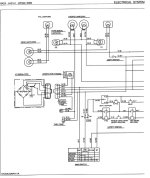
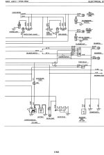
There are two wires feeding to the stop solenoid, a white and a black. The black is tied to permanent ground and the white is connected to the Timer Relay which is located under the dash.
The timer relay controls the voltage to the stop solenoid. The timer relay has two different input voltage circuits that control it. One input circuit has a 15amp fuse and is always hot.
The other input circuit has the 20amp fuse and feeds through both seat switches and the pto switch, the HST pedal switch and is turned on/off via the key switch.

The reason for two inputs to the timer relay is two fold. The always hot input is the actual working voltage that is passed on to the stop solenoid.
The other input that goes through all the safety switches is used to actuate the timer relay and also to power the delay timer circuitry. This is the "control" circuit.

When all the safety switches are in the correct positions (made or shorted contacts) and the key turned on, power is applied to the timer relay though the control circuit. There is NO 12v applied to the stop solenoid. The engine is started and the stop solenoid stays in its unpowered unenergized state.
If one raises up from the seat and with the pto engaged (except in the rear only position) and/or depresses the HST pedal voltage is removed from the timer relay "control circuit" which inturn causes it to immediately apply 12v to the stop solenoid for approx 10 sec's, then the timer relay clicks off and voltage is once again removed from the stop solenoid. 10 seconds is plenty enough time to shut down the D905.

When the key is turned Off it basically removes 12v from the timer relay in the same manner as a safety switch "tripping" which causes the timer relay to apply approx 10 sec's of 12v to the stop solenoid.

Well thats my theory of operation so lets get to some troubleshooting tips.
1) unplug the stop solenoid and using a multimeter or even a 12v lamp, plug one lead into the black recepticle and the other lead to the white recepticle.
Turn the key switch on, you should NOT read any voltage. If you do the timer relay is bad. (note, I've not read of one of these ever going bad yet but anything can fail).

2) Now turn the key switch off. You SHOULD read 12v for approx 10 sec's then it should go away. You will also hear the timer relay click under the dash. (it is not as loud as the stop solenoid click but you can hear it click).
If you do get this reading then your stop solenoid is bad.

3)If you do not get 10 sec's of 12v then the timer relay is bad OR one of the safety switches are not "making" OR(and more likely) the 20amp fuse is blown. The 15amp fuse could also be blown but the 20amp fuse is the main culprit as it also feeds the aux "hot" connector located under the seat that alot of folks like to use to power ROPS lights etc.

Good luck and let us know what you find.

Hi Volfandt, You helped me out on the HST problem and now I found this thread. I thought my timer relay was bad and went to the dealer to pick up a new one. I checked the ohm reading at the dealer on my relay and the new relay gave me the same readings. So I did not purchase it. I then found this posting of yours and just ran the test that you mentioned about pulling off the wires to the solenoid and checking out the timer relay. Mine works exactly as you mentioned. So it appears that the timer relay is fine. My problem is that I can start the tractor without engaging the seat switches. They have no affect on stopping it either. I don't know what is the next thing to check. I sure could use your help again. We apparently have the same tractor, except they had a light bulb that stays on that reads HST, which is located just below the glow lamp light. Do you have any ideas of why the seat safety switches do not have any affect on the starting or stopping of the tractor. I originally couldn't stop the tractor and found out the 20 amp fuse was blown. I can stop it now with the key. All the other fuses are working. Not sure what else to check, all the lights work. I am at a loss here. I thought it was that relay, but apparently not.

Thanks again. jim
 
   / BX23 solenoid location #29  
I dont know about the BX23 but my BX24 is able to be started without being on the seat. Always has. The dealer told me this is normal. The only time the tractor should shut down when you get off the seat is when you get up and the PTO is engaged (unless its flipped up like your using a chipper) or the HST pedal is moved. Those are they only ones I found so far.
 
   / BX23 solenoid location #30  
I dont know about the BX23 but my BX24 is able to be started without being on the seat. Always has. The dealer told me this is normal. The only time the tractor should shut down when you get off the seat is when you get up and the PTO is engaged (unless its flipped up like your using a chipper) or the HST pedal is moved. Those are they only ones I found so far.

That is the first time I have heard that. I wonder if that is the way the BX23 is suppose to be. If so that would have saved me lots of trouble trying to find out why this machine can be started without being seated. Thanks for that information.
 
 
Top