Grapple project OPEN SOURCE

   / Grapple project OPEN SOURCE
  • Thread Starter
#31  
Ok, one question plz. As it looks like there are only details left to be done

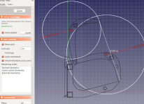
a) About the cylinder. Is it a good practise, when the cylinder extends full, the tips of lids to be just before the tines , exactly, or meet the tines just before it extends fully? I mean will it shorten the life of the cylinder (I doubt it since the tines will have some flexibility anyway)? I guess pinching will be a usefull thing.
 
Last edited:
   / Grapple project OPEN SOURCE
  • Thread Starter
#32  
Question #2 :)
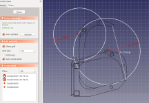
Take a look at these 2 different designs. It shows the tines both opened and closed. The white measurement is the opening to grab material. The white circles with the red measurement is the cylinder in the fully retracted and full extended position.
At the 1st image I used this cylinder with 4" bore, 2nd image with 6" bore. They cost the same.

The main difference that I think that is important is the place that the base of the cylinder mounts the grapple. With the 6"cylinder its about 1.5" higher. If I recall well from my high school, by having the base of the cylinder higher it will create more torque correct? Since the distance from the pivot point is longer.

Would you go with the 2nd design approach too? I feel more clamping force will be a good thing. Any other concerns on that matter?

Thank you guys!
Screenshot from 2017-10-27 08-42-25.png
Screenshot from 2017-10-27 08-40-13.png
 
   / Grapple project OPEN SOURCE #33  
When you said 4" bore and 6" bore think you mean stroke.

Both of your designs are gonna have very minimal clamp force because your pins are two much in align.
 
   / Grapple project OPEN SOURCE #34  
When you said 4" bore and 6" bore think you mean stroke.

Both of your designs are gonna have very minimal clamp force because your pins are two much in align.


Yep, I noticed that in his second drawing. It portrays using a 4" stroke to complete cycle. It will have almost no clamping force in the first half of the cycle from open to closed. The cylinder stroke needs to be 8" or more. The more, the stronger.

This example is where the designer meets the fabricator/user. As the latter, the fact that the former doesn't already see that gives me little comfort. :)
 
   / Grapple project OPEN SOURCE
  • Thread Starter
#35  
Thank you guys, I will redesign it with more distance between the pins
 
   / Grapple project OPEN SOURCE #36  
Thank you guys, I will redesign it with more distance between the pins

I'll assume you simply misquoted. The distance between the pins isn't the problem exactly. I'll let you correctly describe what needs changed. :)
 
   / Grapple project OPEN SOURCE #37  
I'll assume you simply misquoted. The distance between the pins isn't the problem exactly. I'll let you correctly describe what needs changed. :)

Hopefully he'll, um, leverage what he's learned on these forums.
 
   / Grapple project OPEN SOURCE #38  
   / Grapple project OPEN SOURCE #39  
One thing that can be frustrating about hydraulic cylinders is how much space they can take up when retracted.

Not sure if you already know this or not, but there are two types, single acting (commonly used on snow plows and some dump trucks) and double acting. Double acting take up more space, and require twice as many hoses...but move under power in both directions.

One of the easier sizes of cylinder to find, often cheaply or scrounged from other equipment is sometimes called an "ag cylinder", and has a 2" bore and an 8 or 10" stroke. Very common to see them used for simple things like wheels on disk harrows, and they are freaking everywhere. Shorter lengths are usually going to be harder to find, and may even be more expensive. 2-1/2" and 3" bore are available too, but they will be heavier. Every pound at the end of your machine counts against you.

Places to source from:
Look at
Surplus Center
Bailey Hydraulics
and look at the specifications for retracted and extended lengths. Also look at the pin sizes. It's not a bad place to start from to draw two circles centered on the base pin and design your mount locations and lever lengths from there.

The other nice thing about ag cylinders is the retracted and extended lengths are often the same across brands, which will make your design more useful for more people.

As to your other question, I think you are better off planning to have a little pressure on the tips to squeeze. The hydraulics will go to "relief" and stop pushing when hard resistance is met to protect the pump, valve, and cylinders, and the pinch is a very useful thing.
 
Last edited:
   / Grapple project OPEN SOURCE #40  
Hint #1: calculate the force of a hydraulic cylinder in an angle.

Hint #2: your 3 pins comprise a triangle. That is your cylinder angle to figure above.

Hint #3: the grapple teeth are beyond where the cylinder is pushing on them. Simple leverage once you figure out #1 and #2 and you will arrive at your bite force. Which as you have designed now....will be nil
 
 
Top