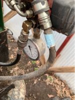
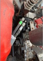
After finally getting time to revisit this problem, I did as Harry suggested and got a pressure gauge, and installed it on an extra input port of the loader joystick controller (as instructed by Eric from Brand Hydraulics, the maker of the controller). Eric told me that if my hydraulic system was "closed center", I would see pressure on the gauge as soon as I started the tractor, and if it was an "open center" system, I would see pressure register on the gauge when I moved the joystick to any (non-neutral) position.
The result was that no pressure showed up either way.
However, when I raised the 3pt hitch control, the pressure on the gauge (still mounted on the joystick control valve) shot up to 2000psi and stayed there as the Yanmar relief valve (the one on the tractor itself) squealed (as always happens when the 3pt reaches top of its travel and lever is still held in the 'raise' position).
Given that the joystick controller was now getting pressure in this condition, I tried simultaneously operating the loader joystick, and then the loader moved. But as soon as I moved the 3pt lever back to neutral, the pressure to the joystick controller went to zero and of course the loader no longer operated.
So I at least confirmed that the hydraulic pump is working fine, but I'm still stumped by how the flow to the loader valve has changed like this (now requiring the 3pt to be in the raise position, where it never had to be before). I've been trying to locate a schematic map of the hydraulic system on this tractor but haven't had much luck so far. Also tried calling Hoye tractor, but Aaron is no longer there (sold the business) and the people there now didn't have any insight into my problem. They only suggested me to check the hydraulic lockout valves (which are both open), and also mentioned that "perhaps it was a line clogged somewhere". But there's only one line supplying the loader valve, which is connected to the divider block on the right rear fender. Previously there was always pressure flowing in this line whenever the engine was running, but now it apparently only reaches this line when the 3pt lever is raised.
View attachment 850605
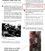
I did manage to find this map, though it's not the most user-friendly. The path looks like the divider block circled in red (where the loader input hose is connected) is a straight shot just directly downstream of the hydraulic pump (D), while the "control valve spool" ("M", that I guess operates the hydraulic lift cylinder) is all downstream of the output block, and in fact appears to actually get all its fluid after first going through that block. So it doesn't seem to make sense that the loader valve can only work/get pressure when this (downstream) control valve spool is opened. Unless there was some kind of backflow going on.. but the diagram doesn't seem to show this would be possible..