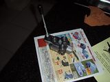
Hydraulic valve for grapple... what one?

   / Hydraulic valve for grapple... what one? #11  
That valve you have only looks like a 1 spool valve.

P usually= PRESSURE
T usually= TANK
B usually= Beyond (or PowerBeyond)

Since there is 2 P's and 2 T's, I think you could use either and plug the other.

You did not get a schematic with it?
 
   / Hydraulic valve for grapple... what one?
  • Thread Starter
#12  
I wish it came with schematics. It didn't even come is a box. It PB sleeve for sure goes in the #8 T port. Both T ports are much smaller on the inside so this must be the pressure side. Restriction = Pressure. I'll plumb the pressure line to the #6 T port. From looking at the insides it seem fluid will go through #6 T, through the valve body, do its thing, and also be redirected out the # 8 port for the PB. This leaves the #6 and #8 P ports for the return line. I'll plug the #6 P and use the #8 as the return.

I hope this makes sense, to me this sound right but for someone reading it I could see how it could be confusing.

Here is a link to the online PDF file for princess auto. The valve I bought (BM20) is on page 16. http://www.princessauto.com/downloadz/DLcaller.cfm?DLS=EXT&TheFile=12hyd

The valve is made in Italy. That could be why the P, T, A, B are backwards compaired to north american valves.
 
   / Hydraulic valve for grapple... what one? #13  
Looks like you got single spool 3 position, 4 way valve item #1249531, is that right? I think it controls 2 cylinders like for a backhoe. That is why there are four #6 ports on top. At least that's what I think. I would call them up to verify the plumbing. That is my advice.

Anyway, I copied your last picture.


OK, so this is what I think...Looking straight down at your valve, with the joystick on top. There are four #6 ports on the face (wide same surface) and one #8 port on each side of the valve....6 ports total.

- Use the two #6 ports that are right below and in line with the joystick to power your new hydraulic cylinder. I think they are activated by the joystick in opposite directions up or down.
- Or use the two #6 ports that are to each side ... them being controlled by a sideways movement of your joystick.
- Plug off either set that you are not using.
- The #8 port on the right side of the valve should be where your power comes in from the pump.
- The #8 port on the left side should be where you install the power beyond sleeve and then hook it up to your fel valve from there.

That does not leave a return to sump then. Like I said above, I'd call them to verify the plumbing.
 
   / Hydraulic valve for grapple... what one?
  • Thread Starter
#14  


3RRL said:
OK, so this is what I think...Looking straight down at your valve, with the joystick on top. There are four #6 ports on the face (wide same surface) and one #8 port on each side of the valve....6 ports total.

That is true. 6 ports total. 4 are #6 ORB 2 are #8 ORB

3RRL said:
- Use the two #6 ports that are right below and in line with the joystick to power your new hydraulic cylinder. I think they are activated by the joystick in opposite directions up or down.

The ports labled A & B will be the working ports.

3RRL said:
- Or use the two #6 ports that are to each side ... them being controlled by a sideways movement of your joystick.

There are only 2 working ports (A and B) The other top ports (P and T) are the same as #8 P and T. If I stick my finger in the #8 P port I can see it throught the #6 P port. I can do the same on the T ports but I can use my finger because the T ports are much smaller but they are connected.

Also my joystick only moves front to back, no side to side. The only thing I don't get is why they labled the ports backwards. Every valve I seen pics of have the supply side labled P and the return side labled T

My PB sleeve can only go in the #8 T port so I'm sure the #6 T port is supply.
P port must be return because A) they are attached to the oil gallery for the relief and B) Their orifice size is 4 time bigger thatn the T ports. Small orifice = high pressure (supply) Big orifice = low pressure ( return)
valve003iq5.jpg
 
   / Hydraulic valve for grapple... what one? #15  
Your last photo is great.
What I've seen on my valves is usually the "in" port is on the opposite side of the "exit" or return to sump/tank like you describe. But the power beyond port is normally on the same side as the exit port, ie. opposite side of the power "in" port. that is what's confusing to me and also why there would be one extra #6 port to plug off? Maybe it's for a pressure relief valve? I don't know. But you seem to have a handle on it now, good job.

I'd go for it just as you have described then. I wasn't sure about the other #6 ports or whether you lever could activate sideways or not. You can always switch the hoses if you need to.
 
   / Hydraulic valve for grapple... what one? #16  
kennyd said:
That valve you have only looks like a 1 spool valve.

P usually= PRESSURE
T usually= TANK
B usually= Beyond (or PowerBeyond)

Since there is 2 P's and 2 T's, I think you could use either and plug the other.

You did not get a schematic with it?

Kennyd is certainly correct. I've never seen them marked otherwise.
 
   / Hydraulic valve for grapple... what one? #17  
Yes, I agree Dave.
That's why I think thought the plumbing would be as I described above except there are only 2 work ports A and B, not 4.
The power in should should come from the P #8 port on the left side where 2310guy has it is labeled "return to tank".
The #6 port that he has labeled "supply" should return to sump or tank. The others are correct. That still leaves the one #6 port to be blocked off. Why do you suppose that is?
 
   / Hydraulic valve for grapple... what one? #18  
3RRL,

Many valves can be used with or without PB. With PB, there are three hoses plus the two working ports, for a total of 5 ports being used. Without power-beyond, there is basically pressure in, pressure out and the two working ports, for a total of 4 hoses/ports being used.

I think the poster would be best to get a proper hydraulic schematic or instrutions before proceeding. Sometimes there is a 1/4" plug down in the valve that must be removed or installed to use with PB.

If he decides to hook it up as he is indicating, he should put a pressure relief in line before the valve, and make sure any open hose off the pressure relief is pointing away from him or anyone else...lest they get annointed with oil.:eek:
 
   / Hydraulic valve for grapple... what one? #19  
2310 Guy:

I believe your valve is labeled correctly. Here is why. The relief, if the typical spring and ball or spring and poppet type, is in the circuit right after the pump in and before the power core because the spool, when activated, blocks flow from the power core and thereby creates the pressure in the power core. The passage you see between the relief valve and the port is the passage that connects the relief vavle to the input circuit, not the exhaust circuit. Given the position of your relief valve (and the fact that most valve body relief valves let fluid flow from the tip of the relief valve through internal passages in the relief valve into the exhaust circuit), it seems unlikely that inlet pressure makes it all the way across the valve body from what you call the pump port to what you call the tank port.

Further, most PB sleeves/plugs are at the end of the power core, so that they block exhaust fluid from returning to the tank. Therefore the port with the machined boss for the PB sleeve o-ring is at the exhaust end of the power core, not at the pressure end. That is, the PB sleeve goes into the tank/exhaust/outlet port, not the pump/pressure/inlet port.

If I am correct, and you hook it up the way you plan, you will be putting full pump pressure into the exhaust/low pressure core, and the relief valve will not work because the pressure in pushing the ball/poppet into the seat rather than trying to lift it agains the spring. And, the exhaust core is usually designed for lower pressure than the power core. Full pump pressure in the exhaust core will put that pressure on the sealing o-rings and likely blow them out. That might be a blessing because if the 0rings hold then full pump pressure will build in the exhaust core and, since its walls are usually thinner than the pressure core walls, the valve body may rupture.

I may be all wrong, but there is chance enough that I am at least part right that you should get someone knowledgeable to look at it first hand before you hook it up and try it. Your pump system relief (assuming you have one) will probably protect the pump and lines, but you could damage your valve or yourself.
 
   / Hydraulic valve for grapple... what one?
  • Thread Starter
#20  
The PB sleeve goes in the #8 T port. It can't go anywhere else. Both #6 and #8 P orts must be return because the inside veiw show a much larger dia. than the T ports

I going with the fact its made in Italy is why the ports are labled different. They also had american made valve where all the ports are labled like you guys are saying P=pressure T=tank. I should have bought american made but they don't carry the size valve I need. Only valve that does 5gal/min is the greasy Italian brand.

If you guys were running 1/4" supply line what would you want your return line back to tank be? You would want it to be bigger than the supply side right?

If I run the the supply in through P port that mean the return line will be much smaller oriface back to tank. I was always told restriction to flow = pressure. If I have restriction to flow on the return side that mean I will have high pressure on the return.

I went back to princess auto today looking for info on my mystery valve but they had none.

Does this make any sense. Its been awhile sinse I saw a hydraulic diagram. Its the only info I could find on the BM20. This is just general info on the BM20.
generalcar.gif


My valve has a relief, its open center, and it has a Power beyond.
Blb hydraulic - Products - Catalog - BM Series

Edit: Oh yeah, thanks again to everyone for there input. The last thing I want it a hydaulic oil shower.
 
 
Top