I got a Tractor!

   / I got a Tractor!
  • Thread Starter
#51  
p5.jpg

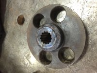
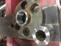
Here is the bored out coupler and the cleaned up spline adapter all ready to become one. I machined the bore undersize so the spline adapter would be a press fit to insure concentricicty and to prevent weld warpage. Turns out it was a good thing I made them fit so tight.

p6.jpg

After I pressed them together, I got a surprise. Up to this point the repair had gone textbook perfect-everything fit as it should and went quick and smooth. But when I went to weld the two togather, I had a really hard time keeping the weld from cracking! I pre-heated the parts evenly, TIG welded with a silicon-bronze rod, and was still getting cracks where the two apparently dissimilar metals ment. Finally multiple passes with silicon-bronze and normal steel rod and wrapping the thing in a carbon fiber blanket to cool slowly kept the cracks to a minimum.
 
   / I got a Tractor!
  • Thread Starter
#52  
p7.jpg

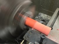
I couldn't find a suitable vibration damping bushing pre-made to replace the old dried up ones, so I made some out of high temp silicone tube. The I.D. was good, but the O.D. was just a little fat-so I skinned it in the lathe.

p8.jpg

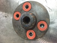
And here is the finished repair. I sure wish a LoveJoy coupler would have just fit ion the space there was!
 
   / I got a Tractor! #53  
I wish I had your skills, equipment, and time!
 
   / I got a Tractor!
  • Thread Starter
#54  
pm1.jpg

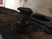
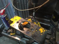
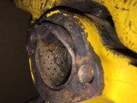
Here is what the front motor mount pin looked like. I don't really know why this was designed like this in the first place-the pin ios welded in, sits metal-to-metal with the front pump/motor mount, and has no means of lube or replacable bushing. Dumb.

pm3.jpg

The hole in the mount was nearly as worn, so I determined what size I could make everything, clamped the mount in the mill and punched it out with a boring bar and then polished and fit it to final size it with a brake hone. I also had to cut the pin out of the tractor frame (which required removing the front axle) and carefully gring the welds away to punch out the remainder of the pin and give me a clean hole to start over.

pm2.jpg

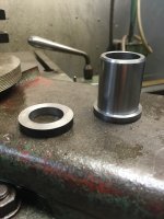
Here is the stressproof bushing and washer I made to replace the old pin.

pm4.jpg

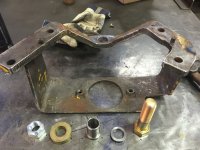
And here are all the parts ready to be assembled.

pm5.jpg
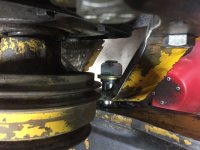
And here it is all put togather! Now if the pin bushing wears out, a new one can be machined and put into place with out major disassembly.
 
   / I got a Tractor!
  • Thread Starter
#55  
f1.jpg

The front end, of course, had it's own issues. Here is what the bushing looked like on the left steering knuckle. The pin didn't look a lot better.

After a LOT of internet parts searching, wearing the local NAPA guy out pouring over front end manuals, and generally being frustrated-I found a complete front kingpin kit that is actually for an old '40 something International truck that uses the same bushings and goofy diameter (1.123, IIRC) as this tractor. The new kingpins are actually too long, but every other dimension is good, so I figure a chop saw will fix the pin length.

I will revisit the front end later when I swing it back under the tractor.
 
   / I got a Tractor!
  • Thread Starter
#56  
r1.jpg

By this point, I have rebuilt every ram on the thing, as well as some other hydraulic parts. Here are some random photos of that action.

r2.jpg

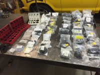
In the process, I seem to have accumulated a bunch of O-Rings and the like.

r3.jpgr5.jpg

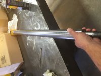
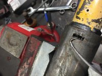
I also had a couple of the dreaded lock-wire style rams to work on. Anyone who has ever gotten to work on one of these where the lock wire has a broken tang knows what I'm talking about here.
 
   / I got a Tractor!
  • Thread Starter
#57  
Now, the radiator.

First off-it was a wreck. But, no suitable replacement could easily be located, so my local radiator guy patched it back together as best as he could. here it is after he got done with it-
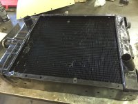
fs1.jpg

The factory shroud was long gone by the time I got this, so I decided seeing as I was making a career out of this tractor, I may as well build a new shroud. That and it gets hot here-the last thing I need is an overheating motor.

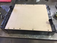
So, the first step was to take some heavy card paper and cut it to the proper size, then punch out bolt holes and bolt it to the radiator-
fs2.jpg

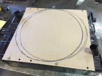
The lines are reference lines that I use to measure. More on that in a sec. Then, I bolt it up and mark out where the fan is in relation to the radiator. This one is tricky, as the fan is not fixed-to tighten the fan belt, the fan moves. The two different circles represent the two extreme locations of the blades-
fs3.jpg

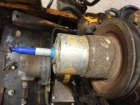
That gives me a baseline idea of where the fan will be, but to get a more accurate measurement, I really need to know where the exact center of the fan is in its different positions, so I deployed my secret weapon-a Sharpie cut down and carefully taped up to the proper diameter and then inserted into the pilot hub for the fan-
fs4.jpg

So, back to those lines and measurements. Off of one point on the paper template, i use a square and graph out an X/Y coordinate map of all the points on the template. Then I put those points into my rusty-trusty computer, draw a bunch of other computer shapes, scratch my head a bunch, and then turn loose my favorite tool-well, favorite tool other than my beer bottle opener!-
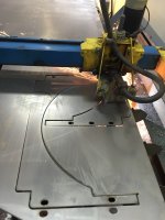
fs5.jpg

Then a bunch of careful bending, careless swearing, and welding and a fan shroud begins to finally take shape. This is a two piece design, which is how I always make them-SOOOOOO much easier to work on!-
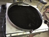
fs6.jpg

And here it is nearly complete and ready to bolt in the tractor and final fit-
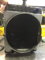
fs7.jpg

Now, the original design had the radiator bolted by the bottom to the tractor frame with a few rubber washers, and the top was solid mounted with some rather poor brackets to the top of the tractor frame. A poor design and a recipe for disaster. In off-road applications, and most on road ones for that matter, you need to allow the radiator to move and float just a little to keep chassis flexing from fatiguing the radiator to death. The half-solid half rubber factory abortion may explain why the radiator was so hammered. So I added rubber bushings all the way around and beefed up the shroud in such a way as to keep the stress out of the radiator itself as much as possible. Here is one of the upper mounts tacked into place-
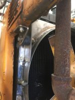
fs8.jpg
 
   / I got a Tractor!
  • Thread Starter
#58  
I wish I had your skills, equipment, and time!

I am fortunate to have a rather unique skill set, and an awesome set of tools. Time, however, is the one thing I have so little of. I just don't sleep much!
 
   / I got a Tractor!
  • Thread Starter
#59  
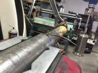
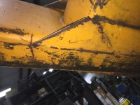
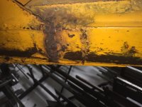
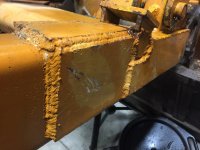
Now, when I bought the tractor, one of the first things I noticed was that the front end loader boom had been repaired repeatedly and poorly. I was going to fix it, then, in the interest of just finishiong this thing and getting on with my life, i had decided to just let the mess ride. That is, until a friend of mine who works on heavy equipment for a living came over one day and looked at it. Now, he's the kinda guy who will let things slide if need be and be like "Ahh, what's the worst that could happen? Run it!" So when he took one look at it and said "WHOA!!! That's bad!" I decided I had better address it. Turns out it was probably a good thing, even though it was sure time consuming.

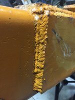
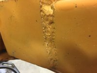
What follows is a bunch of photos showing the boom cracks, poor welds, undercut base metal at the welds , and just general ugliness-


View attachment 452117a4.jpga3.jpga2.jpga1.jpga5.jpg
 
Last edited:
   / I got a Tractor!
  • Thread Starter
#60  
So, I hatched a repair plan.

First, I knew I would have to cut all the old repairs off. I knew that would be hard, but it ended up being WAAAAAY more difficult than I thought it would be.

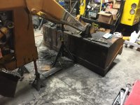
It. Took. ALLLLLLLL DAY! I'll spare you the details, but here's what the place looked like when I finished-

a6.jpga7.jpg

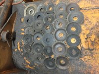
As you can see, I spent a few bucks on cut-off wheels.

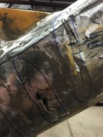
Here is what it looked like under the "repairs". I circled the cracks/breaks with a blue marker. Both sides of the loader arm had been broken clean in half on at least one occasion, probably twice on the right side!-

a8.jpg


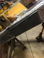
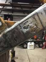
So to begin the repair, I decided to cut out the worst of the broken areas and replace with fresh steel before I over-plated it. So I made this little template for my hand-held plasma cutter and tacked it on to the arm-

a9.jpg

Then I cut around the template-

a11.jpg

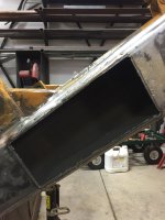
After removing the cut out and cleaning the edges for welding it looked like this-

a102.jpg
 
Last edited:
 
Top