Backhoe Jinma LW-6

   / Jinma LW-6 #21  
Well, the first pic looks like a backhoe with a separate hydraulic pump - not a PTO pump, but one that bolts on above the PTO shaft.

Second pic: I dunno about those, sorry.

Third pic: Yes on the relief valve and the other one may be the power beyond port, (to power another downstream device), for which you'd have to have the PB sleeve installed. Not sure, but it might be.

Fourth pic: I dunno, again. Mine doesn't have that; just the banjo fitting for the line to the sump.

Fifth pic: Makes me think there might possibly be a strainer inside that cannister. Or not.

Rich
 
   / Jinma LW-6 #22  
#1) Tang drive pump. Runs at engine speed (no choice).
#2) Valve on the right is the system relief. Valve on the left is something I didn't have on mine, but it appears to be (maybe) on the boom valve.
#3) I think Rich called it. That appears to be in the correct location on the valve block to be a power-beyond port (that valve may have many applications). The other valve is a relief.
#4 & 5) Is presumably a cleanable strainer because the inlet is opposite of the end opening. If it's a filter cartridge, then the inlet would be next to the end opening.
 
   / Jinma LW-6 #23  
Sounds like you have plenty of flow. If the boom valve has a separate relief it might be the culprit. Install a 3000psi (200 bar) or greater gauge between the pump outlet and valve inlet usint a T fitting. It will show relief pressure when you operate any circuit until it is against the stop. The reliefs should be set at about 140 - 170 bar or 2000 - 2500 psi.
 
   / Jinma LW-6 #24  
Install a 3000psi (200 bar) or greater gauge between the pump outlet and valve inlet usint a T fitting.
And please make sure you use only hydraulic or schedule 80 pipe fittings - no hardware store stuff!
 
   / Jinma LW-6 #25  
Yep, that first pic is a flange mounted hydraulic pump. It dosn't slip onto the splined PTO shaft, but bolts to the back of the tractor case(have to remove 4 bolts and a cover plate to install it?). It basically connects to the shaft that runs right thru the gearbox and up to the PTO clutch. That is the shaft that inputs torque to the 540/720 PTO gearbox, and that shaft turns at engine RPM, so 1500-1800 engine RPM should be plenty to run this pump.

The second pic, I agree with Bob, that looks to be the BH relief valve on the far right side of the pic. That second valve is connected to the left-right axis of that joystick control lever. If that joystic lever is for boom up and down, then the side to side axis of that joystick is most likley boom swing. If so, that is either a safety relief valve for the boom swing circuit, to help keep you from damaging the swing structure(weakest on the BH), or help keep you from rolling the tractor over with too much boom side force. It could also possibly be a flow control valve for the boom swing. I know on mine, the swing cylinders are the smallest on the tractor. They also don't have a very long moment arm to the boom pivot point. What all this adds up to is cylinders that fill and move much faster than any other cylinder on the BH, and which a small ammount of cylinder travel = a lot of boom swing. This makes for a boom swing that is way faster than any other travel on the BH. It is also the weakest circuit/activity...
 
   / Jinma LW-6
  • Thread Starter
#26  
Hello all,
I finally had the opportunity to look further into the problem, I recieved a gauge and then had a great deal of trouble trying to find fittings to connect to the loader - none could be found, it's apparantly a new Chinese thread. So I did a very basic weld job with the spares in the tool kit. Here's the results. I did think that it was only a problem withthe boom up but it seems that it's an overall low pressure situation, jsut more apparant with the boom up movement as ther is more weight.

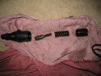
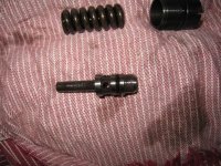
The first pic you see is the pressure relief valve I took apart. This looks nothing like the PRVs I have seen on the forum, it's like something is missing and the spring has very little available movement in it. The rest of the pics are the pressure readings.

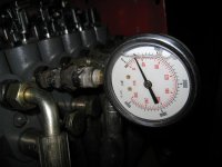
I connected the gauge to the port that tucks in the front arm of the backhoe. With the PTO at 750rpm speed I firstly took a reading at idle -approx 800rpm with the control level push forward fully. It came out at about 400psi. I held the lever for about 15 seconds.

Then I upped the revs to 1000rpm and it went up to 800psi. At 1500rpm it spiked at about 1600psi for a second, then fell back gradually to around 1400psi within a few seconds when I continued to hold the lever forwad.

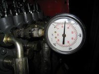
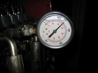
At about 1900rpm the needle spiked at about 1950psi, then did the same thing and fell back within a few seconds to around 1700psi.


I'm surprised at this, not sure what this means. It seems to me that the only reason the needle would show a reduction in pressure after spiking up is becasue the pump is unable to hold the pressure??? After the initial surge in engine rpm, the pump suddenly puts out a burst of pressure but then the fluid back pressure causes the pumps to slip internally. That's my thinking at the moment. I'd like you ideas on how these pumps work. Can they hold pressure irrespective of RPM or do they need high RPM to put out working pressure? This is a pump that attaches to the PTO shaft (see earlier pics) I think it's a pretty standard pump that comes with these backhoes.

I did screw the PRV all the way in after the first run revealed a pressure of 400psi. But as you can see I don't think the fluid is even getting to the relief pressure. Also could this be some kind of checkvalve issue? where is the checkvalve? I don't see that PRV unit having a checkvalve built in. I'm thinking it's either a crap pump, and this is just how the pump is, or the pump is stuffed, or somehow this all points to the PRV but I can't see how with the readings from the gauge.

I also tested for oil bypassing the cylinder seals. no bypass at all, seals are fine.

ANy thoughts and suggestions are greatly appreciated.
 

Attachments

  • prv valve taken apart.JPG
    prv valve taken apart.JPG
    138.1 KB · Views: 232
  • inside prv closeup.JPG
    inside prv closeup.JPG
    154.8 KB · Views: 188
  • idle pressure.JPG
    idle pressure.JPG
    58.7 KB · Views: 199
  • 100orpm pressure.JPG
    100orpm pressure.JPG
    56 KB · Views: 175
  • 1500rpm pressure.JPG
    1500rpm pressure.JPG
    49.8 KB · Views: 170
   / Jinma LW-6 #27  
Please give a description of how you have the pressure gauge connected or a picture. Is it on a T allowing pressure to flow through to the valve?
RonJ
 
   / Jinma LW-6
  • Thread Starter
#28  
The pressure gauge is as conected in the picture. It's not on a tee, just screwed straight into the outlet, are you able to see the thumbnails in the former post?
 
   / Jinma LW-6 #29  
Trelli, that setup won't work for what you are trying to do. The gauge must be tee'd into the circuit as Ron said.
 
   / Jinma LW-6
  • Thread Starter
#30  
I'm trying to find out what sort of pressure it's putting out. I thought that if I connect it straight into the block and opening p the valve it would effectively be like a cylinder piston at maximum position?? I am a novice with hydraulics, how else can i find out what the pressure is?
 
 
Top