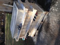
Ken, attached are pictures of the steel framework inside the block of cement. 36, 60 lbs bags of cement mix.
No other steel in the block. <snip> I waited 3 weeks before using it so as to let it set properly. One of the pictures shows it filled with concrete, I wrapped it with 2肺4 to keep the sides from blowing out. The form is 3/4 plywood.
Thanks, FSM5065
That's an impressive framework.
A few more questions, if I may....
36 x 60 lb bags of concrete = 2,160 lbs plus the weight of the steel! That's a heavy block! What are its dimensions?
What is the perpendicular distance between the centres of the upper holes and the lower holes?
I am still a bit confused about the bolts. I can see that the bolts are holding the framework to the ply, which would provide the stability required for the pour (although there seems to be more bolts than would be required to simply stabilise the ply.
In the final product, the ply has been removed. But there are still bolts. Did you replace the bolts for pure aesthetic reasons or was there some other reason?
Interestingly, while awaiting your reply, I did a bit of research about the feasibility of simply bolting a framework to a concrete block. A 1/2" sleeve anchor (3/8"bolt) has a tensile strength ranging from 2,200 lbs to 4,400 lbs, depending on the compressive strength of the concrete. I assume these figures are for a static load. Perhaps, a concrete block bouncing up and down subjects the anchors to different forces and the tensile figures can't be extrapolated from static to dynamic loads.
Even if one used only 25% of the tensile strength figure, by simply adding a sufficient number of anchors one should easily be able to support the block on a frame that is bolted to it.
I aim to get my block up to somewhere around 800kg (1,760 lbs) (after seeing your numbers I am inspired to go even higher) using as many brake rotors and other bits of steel I can encase in it. If one uses the 2,200 lb figure for low compression strength concrete, and divides that by four, that means one anchor can support 550 lbs. That, in turn, means three anchors should suffice for a 1,760 lb block. With six or eight anchors one should easily be able to support the block.
Am I missing something here?
The the outer slots are for a Cat II tractor and the inner one is Cat I.
As a newbie tractor owner, I don't quite follow this. Is this about the distance between the arms or about the hole sizes?
Cat I=7/8"(22mm) and Cat II=1 1/8" (29mm). If you put the Cat II balls in the outer slot, the pin diameter has to be 1 1/8". That means the holes in the outer and the middle plates have to be 1 1/8". If you put the Cat I balls in the inner slot, the pin diameter has to be 7/8". This means that the hole in the inner plate has to be 7/8". Does the pin you are using have two diameters - 1 1/8" between the handle and the inner plate position and 7/8" between the inner plate and the end?
Did you bevel the corners for aesthetics or for some functional reason?
Ken