My apologies and thanks all in one
I apologize to everyone who was confused by my multiple threads. This is my first time working and reporting on an on-going project. This fact accounts for two of the threads. worse, each time I tried to attach pictures, I failed to get them attached properly so I started a new thread to get the pictures out there. This doubled my threads. I was not trying to be rude, I was just an little inexperienced.
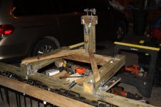
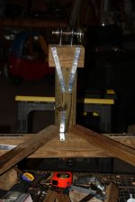
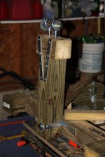
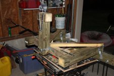
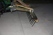
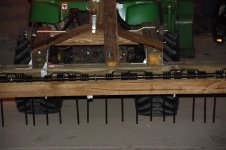
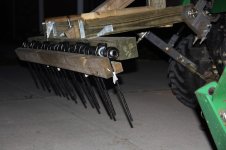
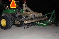
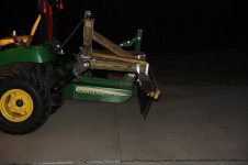
I am, however, going to attach some pictures of my most recent modifications. I substantially redesigned the toplinK connector and I think it is much more secure now that previously. I added a lot of metal strapping to keep everything in place. I also added angle bracing--thanks to all who recommended this--and now all I need to do is to attach the link pins on the lower arms. My plan for this is simply to measure VERY carefully and bore a hole to allow the link ping to fit in. This hole will be drilled from the inside to allow for the rather large nut that attaches to the link-pin. I bought an extra long link pin (extra threading) to ease the drilling. I want to make certain that the pins are perfectly square and even with one-another.
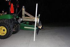
Anyway, here are my most recent modifications. It should look considerably better than it did on the last post. As always, I welcome any insights that I overlooked, missed or just plain forgot.
Thanks in advance,
SI2305
I apologize to everyone who was confused by my multiple threads. This is my first time working and reporting on an on-going project. This fact accounts for two of the threads. worse, each time I tried to attach pictures, I failed to get them attached properly so I started a new thread to get the pictures out there. This doubled my threads. I was not trying to be rude, I was just an little inexperienced.
I am, however, going to attach some pictures of my most recent modifications. I substantially redesigned the toplinK connector and I think it is much more secure now that previously. I added a lot of metal strapping to keep everything in place. I also added angle bracing--thanks to all who recommended this--and now all I need to do is to attach the link pins on the lower arms. My plan for this is simply to measure VERY carefully and bore a hole to allow the link ping to fit in. This hole will be drilled from the inside to allow for the rather large nut that attaches to the link-pin. I bought an extra long link pin (extra threading) to ease the drilling. I want to make certain that the pins are perfectly square and even with one-another.
Anyway, here are my most recent modifications. It should look considerably better than it did on the last post. As always, I welcome any insights that I overlooked, missed or just plain forgot.
Thanks in advance,
SI2305