Thanks for the detailed response Greg.
To be sure I get the process correct I want to go over your instructions step by step.
1)
Hopefully that 6mm won't screw the pooch, but I think you should initially find enough adjustment in the clutch pull rod to set the gap between the release fingers and the bearing face. I just don't know how much that 6mm will affect the ability to subsequently adjust the gap if/when compensating for wear.
-Ha, I didn't think about that.
-Should I go ahead and set the clutch Pack stack height to 105mm as per the manual then?
-What do the dealers recommend?
2)
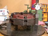
Start your stack height alignment by using the plywood as a flywheel simulator like I mentioned before. You need something with dimensions larger than the clutch pack itself. Place the PTO friction disc on the plywood. Set the clutchpack on the PTO disc. Align the friction discs circumferentially. The 1.2mm gap is for the main clutch discs. Do that first, then add the locking nuts.
-I have done this.
-I used a 1" thick hardened and surface ground flat steel plate instead of the plywood.
-I suspended the PTO clutch and remaining clutch pack on 1-2-3 blocks.
-Then set the 1.2mm gap.
3)
The 105mm depth does not take into consideration the PTO friction disc. And this is not an exacting measurement either, so just add 10mm for the disc. That means you tighten the three black nuts on the fingers to achieve ~115mm between the top of the black nuts and the plywood. Again, this is not micrometer work. It's more important to get it symmetrical than it is to get it exact, which means you might end up with three slightly different measurements; let's say 115mm +/- 1 or 2.
4)
But that's not the end. It's more critical that all three fingers contact the bearing face at the same time, so now you fine tune them. Technically, the black nut should be on the same plane as the finger tips. But if you'd prefer to measure 115mm from fingertips to plywood, that should work too. This is where you'll realize the +/- 1 or 2 aspect.
-I did that, from where the clutch pack would meet (be bolted to) the flywheel (no PTO clutch).
-I thought (from the drawing in the manual) that the 105mm dimension was to the top of the release fingers, not the black nuts?
-The dimension line goes through the black nut and over to the release finger tips (looks like it goes to nuts but does not).
-Next to the 105mm dimension there is the 2mm gap between the release finger tips and the face of the throw out bearing.
-Please check that in your
Tractor Operation Manual and verify.
-Here is the drawing if you can view it.

5)
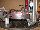
I then got out a 5"x5" piece of plexiglass and a 2' spirit level. Set the plexiglass (or equivalent) on the finger tips, and the level on the plexiglass. Check the bubble between each of the 3 fingers. One will likely be either high or low. Fine tune the fingers till you're within ~1/4 bubble on all three. Then add the locking nuts.
-Instead of the using a bubble level, I accomplished this with a .001" drop indicator and used gage blocks to set all 3 tips within .001" of each other. They are dead nuts.
 Once the tractor is reassembled, make the 3 external clutch linkage adjustments - which includes setting the gap between the finger tips and the bearing face.
-OK, got that.
-Tommy from Affordable told me I can measure from the bell housing to the throw out bearing face on the rear half. Then measure from the bell housing on the engine side to the flywheel. Subtracting the two would give me the distance between the two. Subtract the 2mm finger gap, and that's what to make the clutch pack finger release stack height on the bench. When the tractor is all bolted together, the finger gap should be 2mm.
-So I calculated that and set the stack height.
-BUT ... my question remains about setting the finger height on the bench.
-Clamped together or relaxed?
-The disc springs (behind the pressure plates) hold the clutch pack open. But when the clutch pack is bolted to the flywheel, the disc springs are compressed, right?
-To set the stack height, I don't know whether I should clamp the clutch pack to compress the disc springs or not.
-I figure I should since that's how it is on the flywheel, but I'm asking.
To summarize:
1) Should I use the 105mm stack height or is the 110.8mm OK?
2) Should the clutch pack be clamped on the bench or relaxed to get that stack height?


