Proportional Electrohydraulic Systems??

   / Proportional Electrohydraulic Systems??
  • Thread Starter
#11  
Jer,

I think you can do it. It's not going to be easy, but it sounds like you have available to you what it would take to do it. Personally, the more I think about it, I would try to find an old, or wrecked, or burned up mini-excavator and rape all the parts from it. You could do it with a joystick, but now you're talking getting electronics involved. They do use the system I first talked about in freezers down to -20 Fahrenheit and lower so that's not an issue, but I don't know how they would take getting caught in the rain.

Hmmm. You could use a joystick and pilot hydraulics and switch the pilot circuits with solenoid valves. :)

Andy

Sorry for my ignorance..... but what is/how does a 'pilot' system work?? Is that the one that is sort of the hydraulic equivalent of a electrical relay??

I'm gonna push for it, and follow some of the awesome guides that I've found on here, like Kenny's and Jimgerken, and look for guidance from all the experience here.... We'll see what Otto has to say in early Jan.

-Jer.
 
   / Proportional Electrohydraulic Systems?? #12  
Sorry for my ignorance..... but what is/how does a 'pilot' system work?? Is that the one that is sort of the hydraulic equivalent of a electrical relay??
yes, it is. essentially, you move the stick, that opens a small (1/4"?) valve which sends fluid to open/close a much larger valve. This causes less strain on the operator then directly opening the larger valve (which used to be done with cables that came off the controls, however they often got jammed when working in harsh environments), it also allows the cab to remain cooler as the large (HOT) valvebodies can be farther away from the operator and yes a pilot system is normally proportional

Aaron Z
 
Last edited:
   / Proportional Electrohydraulic Systems?? #13  
Think of a pilot operated valve as a hydraulic amplifier. The input, be it mechanical or electrical, controls a port that uses the hydraulic pressure to control a larger port. This allows a large spool that can handle large flows to be controlled with very little energy input.

My company has designed control systems for snow plow equipment. We use a microprocessor to read the low voltage from the joy stick and convert it to a PWM (pulse width modulation) signal that controls up to about 1 amp of current into a 12 volt servo valve.

You could also do this with no electronics I suppose if you had a hydraulic joy stick of some sort. I don't know much about it doing that way though.
 
   / Proportional Electrohydraulic Systems??
  • Thread Starter
#14  
My company has designed control systems for snow plow equipment. We use a microprocessor to read the low voltage from the joy stick and convert it to a PWM (pulse width modulation) signal that controls up to about 1 amp of current into a 12 volt servo valve.

It's the microprocessor part that scares me the most. I've gotta find out first off if I even need one, second how much it'll cost, and third if I do need one, will a company like Otto or Scorpion pre-make it for me so I could just add it to the system.

I'm hoping that I can safely create and use a system where I am the feedback system. Based on what I see, and the sound I here from the pump and engine I should be able to judge what's going on, no??

Good point on the safety issue, that's something I likely wouldn't be able to incorporate with my limited skillset. Are the servo valves that I'd use for this system prone to these 'stuck-open' failures??

-Jer.
 
   / Proportional Electrohydraulic Systems?? #15  
If you want to do it electronically you'll want a servo valve. The valves I've seen in 12V flavors usually require 1/2 to 1 amp for full flow.

The trick is getting the pot on the joy stick to control the current. The pots are far too small to handle that current directly. The low level of energy in the joystick must be converted to a high level for the valve.

PWM is the most common method because it is very efficient and does not generate much heat like a linear amplifier would.

Most designs today use a processor to accomplish this. The processor output drives an FET (field effect transistor) that switches the 12 volts on/off to the valve. This happens at some higher frequency. The longer the on time the more current flows in the valve. The inductance of the valve filters the frequency to a DC level.

This can be done without a processor. It still requires circuit design. A ramp generator and comparator can convert the joystick to a PWM also.

I have not seen (does not mean there isn't one) a card that takes an analog voltage from a joystick and will drive a solenoid proportionally. There is probably not much call for that since most applications require other features so the designer accomplishes the PWM in the uP. Our system also controls a salt spreader and heads up display as well as 4 PWM outputs and a float solenoid. It has to read vehicle speed as well.

If you want a bi-directional control, I assume you do, you would need to provide a plus and minus power supply to the joystick. Then you could get, say +10 to -10 with 0 at center. A linear amplifier that could accept a +/- 10 volt input and drive the high current +/- 12 volts to the valve would work. There should be some amps like that around.

Our system requires the operator to press a "shoot" button on the stick when moving the stick. That enables the blocking solenoid valve to feed the servo valve. Without that the servo valve will tend to creep when at zero due to small offsets in the circuit and valve. This could be adjusted to zero but it will change with temperature. A blocking valve is safest. Also, if the servo valve spool sticks, as mentioned above, releasing the button on the stick drops the blocking valve and stops motion.

The best approach may be to try to scavange something from an existing machine. That probably isn't so easy either.

I hope this helps a bit.
 
   / Proportional Electrohydraulic Systems??
  • Thread Starter
#17  

Attachments

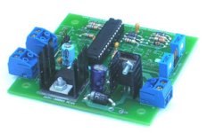
  • solenoid_driver.jpg
    solenoid_driver.jpg
    16.2 KB · Views: 167
   / Proportional Electrohydraulic Systems??
  • Thread Starter
#18  
The trick is getting the pot on the joy stick to control the current. The pots are far too small to handle that current directly. The low level of energy in the joystick must be converted to a high level for the valve.

You're right. The Otto switches run at 32mA, with a 40mA max. I'm actually going to stick with the mechanical joystick I have now, I'm just going to have a custom grip made with the Hall Effect proportional switches to control the featherable circuits I'd like to add, and the one reversible on/off circuit for the blower/broom/auger.

I have not seen (does not mean there isn't one) a card that takes an analog voltage from a joystick and will drive a solenoid proportionally. There is probably not much call for that since most applications require other features so the designer accomplishes the PWM in the uP. Our system also controls a salt spreader and heads up display as well as 4 PWM outputs and a float solenoid. It has to read vehicle speed as well.

Maybe it could control the missile lock I've been wanting too...???!! Do you know of a source for these?? Actually, I think I just found one........

Scorpion Technologies LTD. - Driver Cards

Would that work??

If you want a bi-directional control, I assume you do, you would need to provide a plus and minus power supply to the joystick. Then you could get, say +10 to -10 with 0 at center. A linear amplifier that could accept a +/- 10 volt input and drive the high current +/- 12 volts to the valve would work. There should be some amps like that around.

I do, for sure. The Otto switches look to run from +0.5V to +4.5V.

Scorpion is actually quite close to wear I live, so I think they'll be a good resource.

Really appreciate all the help here.

-Jer.
 
   / Proportional Electrohydraulic Systems?? #19  
Jer
.,

I think one problem you may run into that will be a showstopper is that most of these advanced systems are designed for closed-center hydraulic systems with variable displacement pumps. Your tractor has a open-center system with a fixed displacement pump.
 
   / Proportional Electrohydraulic Systems?? #20  
If you want to do it electronically you'll want a servo valve. The valves I've seen in 12V flavors usually require 1/2 to 1 amp for full flow.

The trick is getting the pot on the joy stick to control the current. The pots are far too small to handle that current directly. The low level of energy in the joystick must be converted to a high level for the valve.

PWM is the most common method because it is very efficient and does not generate much heat like a linear amplifier would.

Most designs today use a processor to accomplish this. The processor output drives an FET (field effect transistor) that switches the 12 volts on/off to the valve. This happens at some higher frequency. The longer the on time the more current flows in the valve. The inductance of the valve filters the frequency to a DC level.

This can be done without a processor. It still requires circuit design. A ramp generator and comparator can convert the joystick to a PWM also.

I have not seen (does not mean there isn't one) a card that takes an analog voltage from a joystick and will drive a solenoid proportionally. There is probably not much call for that since most applications require other features so the designer accomplishes the PWM in the uP. Our system also controls a salt spreader and heads up display as well as 4 PWM outputs and a float solenoid. It has to read vehicle speed as well.

If you want a bi-directional control, I assume you do, you would need to provide a plus and minus power supply to the joystick. Then you could get, say +10 to -10 with 0 at center. A linear amplifier that could accept a +/- 10 volt input and drive the high current +/- 12 volts to the valve would work. There should be some amps like that around.

Our system requires the operator to press a "shoot" button on the stick when moving the stick. That enables the blocking solenoid valve to feed the servo valve. Without that the servo valve will tend to creep when at zero due to small offsets in the circuit and valve. This could be adjusted to zero but it will change with temperature. A blocking valve is safest. Also, if the servo valve spool sticks, as mentioned above, releasing the button on the stick drops the blocking valve and stops motion.

The best approach may be to try to scavange something from an existing machine. That probably isn't so easy either.

I hope this helps a bit.

What is the price and models of the valves you are using? I just did some searching on servo valves. and I was constantly seeing them priced at over $1000 each.
 

Tractor & Equipment Auctions

2014 UTILITY DRY VAN TRAILER (A45677)
2014 UTILITY DRY...
Terms and Conditions (A42021)
Terms and...
2017 Nissan Sentra (A46684)
2017 Nissan Sentra...
2016 NISSAN SENTRA (A46684)
2016 NISSAN SENTRA...
2016 Toyota Prius Hatchback (A46684)
2016 Toyota Prius...
Passport Ultra Lite 2920 BH (A48289)
Passport Ultra...
 
Top