s219
Super Member
- Joined
- Dec 7, 2011
- Messages
- 8,548
- Location
- Virginia USA
- Tractor
- Kubota L3200, Deere X380, Kubota RTV-X
I have been working on putting a roof over my pier for the last 2.5 months, and figured I would post some pictures and information. This was an interesting and challenging project, with some design/planning skills that overlap with pole barns and other structures. I planned and fabricated everything to be a one-man job, as I couldn't bring myself to ask friends or relatives to help with such a complex and time consuming job. I knew it would take a long time and decided to pick away at it as time, day job, marriage/family, and weather allowed. Some days were devoted only to buying lumber and carrying it down to the pier (about 150' through the woods, then down 40 steps).
The basic goal was to put a simple gable roof with 4:12 pitch over my boat slip, which is about 11 feet across and 22 feet long. With overhangs, the roof would cover an area about 15 feet wide and 24 feet long.
The pier already had vertical pilings, some supporting a boat lift. I trimmed and notched the end pilings to height with a chainsaw, and then put up header beams down the sides, and carrying beams across:
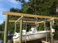
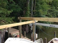
The main point of the cross beams was to help deal with imperfectly aligned pilings, so that I could get the headers parallel and lined up. The tops of the pilings varied in/out by 4-6" on average, with one 12" out of line. So by putting carrying beams across the middle pilings, I could attache the headers to the end pilings and let them fall where they may in the vicinity of the middle pilings. The carrying beams only had to deal with a bending moment over 12" maximum -- sort of just wide "blocks" -- so tripled-up 2x6 lumber was more than enough.
The headers were sized to support a combined roof load of 30 PSF, which is typical for this area. For a section with 12' span, double 2x10 lumber was used. The sections with 4' and 6' span only required 2x6 and 2x8 lumber, but I used 2x10 there and bolted everything together where the components met over the top of the carrying beams. With very careful measuring and positioning, I was able to get the headers parallel within 1/4" over the entire 24' length, which I was real happy about.
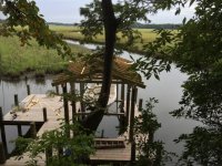
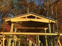
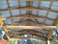
For roof support, I pre-assembled rafter units made up of 2x6 rafters (8' long on the diagonal) with a 2x4 8' cross tie and metal gusset plates at the top. The rafter spacing was 2'. The rafters were notched to sit over the header beams. I was able to lift these rafter units into place, and then setup a walk board across the headers to position and nail in the rafters. I kept sliding the walkboard down along the headers 2' at a time and added rafter units, until all 13 were up in place:
From there, I moved onto purlins, planning to use 2x4 lumber spaced 2' to accommodate loads and properly support the 26 ga metal PBR panel roof. This was the first point in the design/construction process where I began to think about uplift. For non-traditional structures, uplift design is not an easy process, and many projects will run this by an engineer for proper analysis. In this case, I was not required to get a building permit (county keeps their nose out of anything not on land, thankfully) so I was able to do the analysis myself. Unsatisfied with cookbook design, I resorted to my aerospace-engineer training to run a computational aerodynamics simulation of a gable roof. I considered designs with open and closed gable ends, and looked at wind coming at the roof over a range of angles. I found that wind coming towards the corner of the roof was a ideal worst-case-scenario to look at, with a variety of loading features of interest. Knowing the typical gusts we see from hurricanes here, I added about a 25% factor of safety and ran analysis with a wind speed of 120 mph. Here are some plots showing the computed uplift, with wind coming towards the lower left corner. Color contours indicate uplift pressure in PSF:
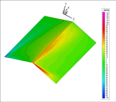
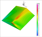
Based on this, I decided to keep a partially open gable to help vent pressure, and to use 70 PSF as my typical uplift value acting over large enough areas to be of interest (higher values were peaky and limited to smaller areas). With that number, I was able to work uplift loads into the design starting from the metal roofing panel, then panel fasteners, then to purlin spacing, then purling-to-rafter fasteners, then rafter to header uplift anchors, and finally to header-to-piling uplift anchors.
In a nutshell, for 2' spacing of purlins and rafters, each purlin-to-rafter attachment would see about 72# of uplift, and each rafter pair would see about 576#. The headers would then each see about 3744# of uplift. That drove me to use two #10 3-1/2" star drive exterior screws for each purlin-to-rafter attachment point, two hurricane clips at each rafter seat (one on inside of header and one on outside, to spread the nails), and then mobile home anchor strap to secure headers to pilings (independent of any existing bolts or hardware associated with the boat lift structure, which would help but is an unknown).
With that worked out, I put up the purlins as originally planned. Due to uplift, I wasn't comfortable with purlin joints landing on a single rafter, as that would put too many screws into a limited amount of wood. So I shifted the purlin joints to fall between rafters, resting on an additional nailer set between the rafters and tied in with a bracket. To handle the peaky pressure loads that showed up near the gable ends in the analysis, I put an extra set of short purlins between the end rafter pairs, to reduce purlin spacing to 1' there and provide additional fastener points for the metal and spread out the load.
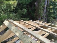
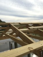
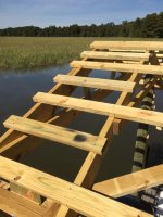
At this point I was finally ready to start putting up the metal roof. However, since I was using all pressure-treated lumber for the framing, including the purlins, corrosion was a concern. I was able to track down hot-dipped-galvanized roofing screws, and decided to put a barrier between purlins and roofing panels based on conversations with the roofing supplier (Mackey metal roofing). I initially planned to use felt paper, cut into 4" strips, and stapled down on the purlins. But putting up a test panel, I discovered that the felt left nasty brown stains on the underside of the panel as it was slid into place, and the edges of the panel kept snagging the felt and tearing it. Working near water with challenging access and constant breezes, I had no time for games getting panels up onto the roof. So I decided to punt on the felt and instead used self-adhesive flashing membrane, 20 mils thick, cut into 3" strips (to make the most of the 6" wide rolls it came in). This would stay put better on the purlins, and provided a barrier between the metal roof and the pressure treated lumber at the critical point where screws pierced through the panels.
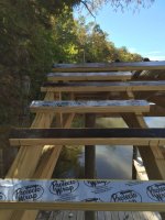
With that worked out, I measured and pre-drilled pilot holes in the stack of roofing panels, as another convenience to get the panel fastened down easily and quickly under challenging conditions. Each panel was hand carried the 150' from my garage through the woods, then down 40 steps to the pier, then up a ladder, then fastened. It went well except for those days when a squall would move through the area, or a breeze would kick up. That stuff happens without warning near the coastline in tidal Virginia, and I just had to deal with it. I skipped days when I knew the weather was going to be bad, and then worked around wind/rain the best I could on weekends and days I could take time off from my day job. It ended up taking about 2 weeks to get all the panels up.
I only had one incident, where a panel I leaned up against a piling blew over while I was putting on my tool belt. I looked up just in time to see it go over the edge of the pier and under the water!! Thank god it landed white side up, close to low tide, so that I could faintly see it. I quickly got in the water (now about 55F this time of year, a nice refreshing dip) and rescued the panel. My wife gave me a funny look when I came in to change clothes, and I just shook my head in the universal "don't ask" gesture....
Once the panels were up, the remaining tasks were basically trim for gable ends and eaves. I ordered standard gable rake trim from the roofing supplier, then rented a metal brake to re-bend it to better fit the purlin ends on the gables and give the desired amount of reveal to framing. They had custom bent me the eave trim to my specs, so that went on easily.
The end result looks good, and I finished just in time before cold weather hit this week. All I have left to do is take down my staging, cleanup scrap, and caulk a few joints here and there. Then I will move on to wiring up some lights under the roof. Next spring, I may add a short skirt of board & batten siding around the edge of the framing.


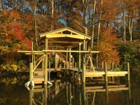
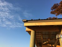
The basic goal was to put a simple gable roof with 4:12 pitch over my boat slip, which is about 11 feet across and 22 feet long. With overhangs, the roof would cover an area about 15 feet wide and 24 feet long.
The pier already had vertical pilings, some supporting a boat lift. I trimmed and notched the end pilings to height with a chainsaw, and then put up header beams down the sides, and carrying beams across:


The main point of the cross beams was to help deal with imperfectly aligned pilings, so that I could get the headers parallel and lined up. The tops of the pilings varied in/out by 4-6" on average, with one 12" out of line. So by putting carrying beams across the middle pilings, I could attache the headers to the end pilings and let them fall where they may in the vicinity of the middle pilings. The carrying beams only had to deal with a bending moment over 12" maximum -- sort of just wide "blocks" -- so tripled-up 2x6 lumber was more than enough.
The headers were sized to support a combined roof load of 30 PSF, which is typical for this area. For a section with 12' span, double 2x10 lumber was used. The sections with 4' and 6' span only required 2x6 and 2x8 lumber, but I used 2x10 there and bolted everything together where the components met over the top of the carrying beams. With very careful measuring and positioning, I was able to get the headers parallel within 1/4" over the entire 24' length, which I was real happy about.
For roof support, I pre-assembled rafter units made up of 2x6 rafters (8' long on the diagonal) with a 2x4 8' cross tie and metal gusset plates at the top. The rafter spacing was 2'. The rafters were notched to sit over the header beams. I was able to lift these rafter units into place, and then setup a walk board across the headers to position and nail in the rafters. I kept sliding the walkboard down along the headers 2' at a time and added rafter units, until all 13 were up in place:

From there, I moved onto purlins, planning to use 2x4 lumber spaced 2' to accommodate loads and properly support the 26 ga metal PBR panel roof. This was the first point in the design/construction process where I began to think about uplift. For non-traditional structures, uplift design is not an easy process, and many projects will run this by an engineer for proper analysis. In this case, I was not required to get a building permit (county keeps their nose out of anything not on land, thankfully) so I was able to do the analysis myself. Unsatisfied with cookbook design, I resorted to my aerospace-engineer training to run a computational aerodynamics simulation of a gable roof. I considered designs with open and closed gable ends, and looked at wind coming at the roof over a range of angles. I found that wind coming towards the corner of the roof was a ideal worst-case-scenario to look at, with a variety of loading features of interest. Knowing the typical gusts we see from hurricanes here, I added about a 25% factor of safety and ran analysis with a wind speed of 120 mph. Here are some plots showing the computed uplift, with wind coming towards the lower left corner. Color contours indicate uplift pressure in PSF:


Based on this, I decided to keep a partially open gable to help vent pressure, and to use 70 PSF as my typical uplift value acting over large enough areas to be of interest (higher values were peaky and limited to smaller areas). With that number, I was able to work uplift loads into the design starting from the metal roofing panel, then panel fasteners, then to purlin spacing, then purling-to-rafter fasteners, then rafter to header uplift anchors, and finally to header-to-piling uplift anchors.
In a nutshell, for 2' spacing of purlins and rafters, each purlin-to-rafter attachment would see about 72# of uplift, and each rafter pair would see about 576#. The headers would then each see about 3744# of uplift. That drove me to use two #10 3-1/2" star drive exterior screws for each purlin-to-rafter attachment point, two hurricane clips at each rafter seat (one on inside of header and one on outside, to spread the nails), and then mobile home anchor strap to secure headers to pilings (independent of any existing bolts or hardware associated with the boat lift structure, which would help but is an unknown).
With that worked out, I put up the purlins as originally planned. Due to uplift, I wasn't comfortable with purlin joints landing on a single rafter, as that would put too many screws into a limited amount of wood. So I shifted the purlin joints to fall between rafters, resting on an additional nailer set between the rafters and tied in with a bracket. To handle the peaky pressure loads that showed up near the gable ends in the analysis, I put an extra set of short purlins between the end rafter pairs, to reduce purlin spacing to 1' there and provide additional fastener points for the metal and spread out the load.


At this point I was finally ready to start putting up the metal roof. However, since I was using all pressure-treated lumber for the framing, including the purlins, corrosion was a concern. I was able to track down hot-dipped-galvanized roofing screws, and decided to put a barrier between purlins and roofing panels based on conversations with the roofing supplier (Mackey metal roofing). I initially planned to use felt paper, cut into 4" strips, and stapled down on the purlins. But putting up a test panel, I discovered that the felt left nasty brown stains on the underside of the panel as it was slid into place, and the edges of the panel kept snagging the felt and tearing it. Working near water with challenging access and constant breezes, I had no time for games getting panels up onto the roof. So I decided to punt on the felt and instead used self-adhesive flashing membrane, 20 mils thick, cut into 3" strips (to make the most of the 6" wide rolls it came in). This would stay put better on the purlins, and provided a barrier between the metal roof and the pressure treated lumber at the critical point where screws pierced through the panels.

With that worked out, I measured and pre-drilled pilot holes in the stack of roofing panels, as another convenience to get the panel fastened down easily and quickly under challenging conditions. Each panel was hand carried the 150' from my garage through the woods, then down 40 steps to the pier, then up a ladder, then fastened. It went well except for those days when a squall would move through the area, or a breeze would kick up. That stuff happens without warning near the coastline in tidal Virginia, and I just had to deal with it. I skipped days when I knew the weather was going to be bad, and then worked around wind/rain the best I could on weekends and days I could take time off from my day job. It ended up taking about 2 weeks to get all the panels up.
I only had one incident, where a panel I leaned up against a piling blew over while I was putting on my tool belt. I looked up just in time to see it go over the edge of the pier and under the water!! Thank god it landed white side up, close to low tide, so that I could faintly see it. I quickly got in the water (now about 55F this time of year, a nice refreshing dip) and rescued the panel. My wife gave me a funny look when I came in to change clothes, and I just shook my head in the universal "don't ask" gesture....
Once the panels were up, the remaining tasks were basically trim for gable ends and eaves. I ordered standard gable rake trim from the roofing supplier, then rented a metal brake to re-bend it to better fit the purlin ends on the gables and give the desired amount of reveal to framing. They had custom bent me the eave trim to my specs, so that went on easily.
The end result looks good, and I finished just in time before cold weather hit this week. All I have left to do is take down my staging, cleanup scrap, and caulk a few joints here and there. Then I will move on to wiring up some lights under the roof. Next spring, I may add a short skirt of board & batten siding around the edge of the framing.


