As far as I can see from the attached diagram, the following is correct.
There's no extra coils in your diagram.
The coils are in the dynamo, they aren't shown, possibly split 4 coils for each circuit.
It's set up to run the lights on AC and charge the battery with DC.
No. I thought that initially, but it appears that if you follow the light circuit, the lights are powered from the "T" terminal of the light switch, the "T" terminal is connected to the "B" terminal which is 12V DC direct from IGN switch/"B" terminal on regulator. Battery is charged via "B" terminal on the regulator as normal when engine running
If the lights aren't on, there's no flow of AC.
No. The AC circuit is brown wire to the "AC" terminal, and yellow wire to "AC" terminal via "S" terminal. Completed AC charging circuit whenever dynamo is spinning.
Additionally, when the light switch is activated, white wire from dynamo to "G2" terminal is connected to "S" terminal to "AC" terminal, adding some output from the dynamo to the circuit.
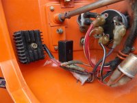
The OP stated there were separate modules for the rectifier and regulator. Perhaps the regulator is used strictly for gauges or something. That's why I'd like to "see" what he has.
Yes, I said this circuit may be similar to his as it has a 3 wire dynamo and additional switching with the light switch. What he actually has, we will have to wait for the pics and info and see.


