how is this valve suppose to work?

   / how is this valve suppose to work? #1  

martini64

New member
Joined
Aug 24, 2013
Messages
12
Location
France
Tractor
Someca 500, Renault 850
I have an old backhoe, which through my rough use, has stopped working. I have been using it for years until at full depth I hit a large rock.
The pressure blew the pump, but I think also the valve I describe below. I have replaced the pump and a piston which got bent, but it is not working.
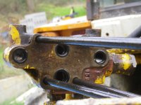
I am pretty certain this one-way check valve (maybe also a relief valve?) is now not doing its job, and is the issue. It controls the pressure and return flow of the oil (I think!).
But, I am not certain how it goes together and so is supposed to work. It fits as a cartridge in the end section of the manifold taking the return line oil in.
It needs to let the oil through itself so that it can come out of the manifold and return to the reservoir, but I don't know how this is supposed to be done.
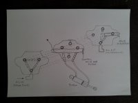
The main cartridge has a conical plug fixed in it. The plug screws on to the cartridge with the spring inside pushing another conical plug against the one in the cartridge.
This seems to stop the flow completely, as there is a rubber "o" ring on the cartridge to stop oil passage on outside. I don't know the function of the plunger.
The attached photo shows the bits, but it is possible I have lost a piece as is spring loaded and shot out in disassembly.
Any help would be greatly appreciated.
 

Attachments

  • IMGP1438.JPG
    IMGP1438.JPG
    2.1 MB · Views: 246
   / how is this valve suppose to work? #2  
That is a pressure relief valve.

What brand is the backhoe?

Do a search online with the model number, for a manual and a parts book.

Somebody here might be able to help, if you post the brand.
 
   / how is this valve suppose to work?
  • Thread Starter
#3  
That is a pressure relief valve.

What brand is the backhoe?

Do a search online with the model number, for a manual and a parts book.

Somebody here might be able to help, if you post the brand.


Thanks for the response. I assume then that the pressure relief valve should be closed in normal operation, and opens when the pressure exceeds the spring strength. I suspect this is what has happened, but when I put it back as I think it was, it seems to block passage of the return flow. I attach a photo of it fitted into the last block of the manifold (in case that helps)

Unfortunately any branding is long gone. In fact it has been cut off the back of an old digger, and adapted via some welding to fit on the three point of a tractor.
 

Attachments

  • IMGP1395.JPG
    IMGP1395.JPG
    2 MB · Views: 180
   / how is this valve suppose to work? #4  
Well it shouldn't block the return flow. There should be no flow through it until the set pressure is exceeded, then it opens and allows flow to the tank.

Here is a diagram of a basic PRV, from a google image search:

PressControlValveFig2.jpg
 
   / how is this valve suppose to work? #5  
In the picture of your first post. Is there still a spool or poppet inside the largest/longest piece?

Is there a small hole in the center of this spool or poppet?

Spring looks large enough to a direct acting relief but possible it is pilot operated style. If the hole in the main spool or ppet is plugged the valve will remain open bypassing all the fluid at a very low pressure.
 
   / how is this valve suppose to work?
  • Thread Starter
#6  
Well it shouldn't block the return flow. There should be no flow through it until the set pressure is exceeded, then it opens and allows flow to the tank.

Here is a diagram of a basic PRV, from a google image search:

View attachment 466668

ok, I see - thanks for this. This is exactly what I need to get to its design.

I don't think it is (just) a pressure relief valve then. The manifold has no other valves and so I guess it must act at least partly as a pressure relief. Could it be acting as a pressure relief and check? When the flow through pressure is too high it could push the spring back and release pressure by oil flowing back through it. In normal operation it simply allows oil to flow through, but stops any return (unless the pressure is high). I am making stuff up here in order to try to understand. I have looked at the design of various valves one gets for diggers, and trying to understand this design.

In the second photo I attached you see the return line in the manifold (on the right) going into the valve in situ. If it simply blocks then there is no return.
Also, it doesn't really explain what the plunger is for.
 
   / how is this valve suppose to work?
  • Thread Starter
#7  
In the picture of your first post. Is there still a spool or poppet inside the largest/longest piece?

Is there a small hole in the center of this spool or poppet?

Spring looks large enough to a direct acting relief but possible it is pilot operated style. If the hole in the main spool or ppet is plugged the valve will remain open bypassing all the fluid at a very low pressure.

Thanks for the response.
There is a poppet inside the cartridge, and it does have a hole in it. This is poppet is the valve seat I guess and is plugged by another poppet that is held by the spring.
I am no expert here so I am afraid I do not understand why the valve remains open. The low pressure return flow of oil comes into the cartridge; I don't understand how it can bypass.
 
   / how is this valve suppose to work? #8  
What are the flow paths or ports connected to this valve?

What you are describing sounds like it could be a pilot operated relief. The main ppot is held in place by the the second pilot poppet and spring. When pressure builds up on the nose of the pilot poppet it lifts off allowing the main poppet to open a flow path from pressure to tank. Some relief valves also have the option of free reverse flow for anti cavitation function. This usually requires a very soft or weak spring to accomplish this.

If the passage in the main poppet gets plugged or a small piece of dirt gets caught on the pilot poppet seat the valve will fail open allowing oil to pass at low pressure to tank.
 
   / how is this valve suppose to work?
  • Thread Starter
#9  
What are the flow paths or ports connected to this valve?

What you are describing sounds like it could be a pilot operated relief. The main ppot is held in place by the the second pilot poppet and spring. When pressure builds up on the nose of the pilot poppet it lifts off allowing the main poppet to open a flow path from pressure to tank. Some relief valves also have the option of free reverse flow for anti cavitation function. This usually requires a very soft or weak spring to accomplish this.

If the passage in the main poppet gets plugged or a small piece of dirt gets caught on the pilot poppet seat the valve will fail open allowing oil to pass at low pressure to tank.

Thanks for all the information and advice. I will draw up the flows and post. I need to educate myself to fully understand what you have said. I still don't understand the function of the plunger, for example. As you suggest i suspect this is a dual purpose valve. This is a 40-50 year old machine, so it is liable to be a basic design. I bought it a few years ago, restored it and it has been a great solid worker. Looking at closest designs i can find, old case diggers, i might just be missing an o ring. I will chase these leads and post when i have better info.
Thanks.
 
   / how is this valve suppose to work?
  • Thread Starter
#10  
Thanks for all the information and advice. I will draw up the flows and post. I need to educate myself to fully understand what you have said. I still don't understand the function of the plunger, for example. As you suggest i suspect this is a dual purpose valve. This is a 40-50 year old machine, so it is liable to be a basic design. I bought it a few years ago, restored it and it has been a great solid worker. Looking at closest designs i can find, old case diggers, i might just be missing an o ring. I will chase these leads and post when i have better info.
Thanks.

Here is a drawing of the flow/connectivity - please excuse the rough drawing; I hope it is understandable, and helps.
 

Attachments

  • pelle_hydraulics_flow.jpg
    pelle_hydraulics_flow.jpg
    1.2 MB · Views: 152

Tractor & Equipment Auctions

Kinze (Delgelman) MT 201 High Speed Disc (A52349)
Kinze (Delgelman)...
2023 Club Car Carryall 700 Utility Cart (A51691)
2023 Club Car...
Land Honor Rock Bucket (A50514)
Land Honor Rock...
CHANDLER CHICKEN LITTER SPIN SPREADER (A51243)
CHANDLER CHICKEN...
TRAILER AXLE (A51244)
2020 KUBOTA RTV X1100C UTV (A51406)
2020 KUBOTA RTV...
 
Top