Aussiebushman
Gold Member
- Joined
- Jul 31, 2008
- Messages
- 252
- Tractor
- Ford 6000
G'Day from Oz
I have a jib that attaches to the 3PT linkage on my Ford 6000 but the usefulness of this is limited due to the lift height and a minor hydraulic leak causes the lift to slam up instead of raising steadily - fixing that is a job for another lifetime!
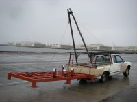
The ground here is uneven and lifting heavy objects gets awkward so Instead of building a fixed crane or gantry, an adaptation of the one in this picture seems like it could be a great solution and I have most of the bits needed including the steel and the chain block. There is no danger of the front of the tractor lifting due to the weight of the massive dozer blade holding it down.
I see the benefits of this concept being its mobility - the tractor and rig can be backed up to whatever needs lifting. The only problem I can foresee is the angle of the wire stay being too far back but I can't see an alternative other than adding a vertical "gin pole" OR running the cable right through the cab to the steel frame at the front - not desirable
Jenna (the German Shepherd in the picture) has already provided instructions but has anyone got a better idea (and I do not mean hiring a crane for a 3 hour round trip every time I want to use it).
I have a jib that attaches to the 3PT linkage on my Ford 6000 but the usefulness of this is limited due to the lift height and a minor hydraulic leak causes the lift to slam up instead of raising steadily - fixing that is a job for another lifetime!
The ground here is uneven and lifting heavy objects gets awkward so Instead of building a fixed crane or gantry, an adaptation of the one in this picture seems like it could be a great solution and I have most of the bits needed including the steel and the chain block. There is no danger of the front of the tractor lifting due to the weight of the massive dozer blade holding it down.
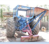
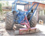
- The two main frames will be made of 75 X 45 mm steel RHS 3 each metres long
- A collar will be made to bolt the two frames together at the head of the rig, control the height and hang the chain block
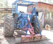
- Holes will be drilled at the bottom of each side frame to swivel on the pins in the 3 pt linkage
- The "back stay" (actually faces to the front of the tractor) will be a heavy cable running from a mounting point on one side of the tractor through an adjusting block and back to the other side - this controls the height of the frame. OR it may be easier to simply affix the head of the rig with chain that can be adjusted for length with a rated shackle .
I see the benefits of this concept being its mobility - the tractor and rig can be backed up to whatever needs lifting. The only problem I can foresee is the angle of the wire stay being too far back but I can't see an alternative other than adding a vertical "gin pole" OR running the cable right through the cab to the steel frame at the front - not desirable
Jenna (the German Shepherd in the picture) has already provided instructions but has anyone got a better idea (and I do not mean hiring a crane for a 3 hour round trip every time I want to use it).
") Also, to connect bits, instead of just punching bolt holes at pivots or anchor points, can you make bigger holes and weld in bushes/hubs? (Tack & try out right on the 3PH and weld 'er up once for good?) t o g
Also, to connect bits, instead of just punching bolt holes at pivots or anchor points, can you make bigger holes and weld in bushes/hubs? (Tack & try out right on the 3PH and weld 'er up once for good?) t o g
