Sorry, this definitely not something I should still be thinking about 4 days later, but this little detail won't stop nagging me; I hope you'll excuse me dragging my own thread off topic.
Do I understand correctly that the alternator is there only as a speed reference to your governor? Or are you using its output for other things as well? I ask because alternators are pitifully inefficient and I assume that efficiency would be something at the top of the list of priorities for this. Could you not use the DC generator as a speed reference? Is your governor something off-the-shelf that is designed to read alternator ripple frequency? Could it accept a different type of frequency input? If you can't use the back-EMF of the DC generator as reference directly, it should be trivial to convert that to a frequency signal using a signal conditioning IC or an Arduino or something. Or even just mount an inductive sensor on the flywheel.
What I am trying to do here is charge a 100v lithium iron battery from natural gas, and do it as silently as possible.
Eventually this will all happen automatically if the battery voltage falls below some critical level. I can just set this up in my garage and forget about it, no refueling required.
Now very small "silent" gasoline generators have been around for quite some time and would be a simple low cost solution, except for one thing. No electric start on the smaller ones, and no easy way to add electric start for fully automatic operation. The larger ones with electric start are incredibly noisy, and definitely not what I want.
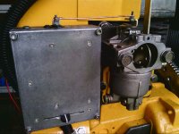
So I decided to resurrect a big old 12Hp Wisconsin, toss out the magneto and rope start, and fit a 12v lead acid starting battery, a 12v car starter motor, a Bosch electronic ignition, and of course a smallish 12v alternator. All that is just to start and run the engine. Cheap, simple, accessible, and very easy to fix. Now to charge the battery there is a separate 100v dc brush type generator. At the moment this is just a rather small treadmill motor, and that may do the job. Or I may fit something a bit larger later on if there turns out to be enough grunt from the Wisconsin.
Now there needs to be a speed governor of some kind, and as I am a retired electronic engineer, that part of it is quite straightforward. The original ignition points only open and close at 10Hz when the engine is doing 1,200 rpm which is rather slow for a nice tight speed control loop. As the alternator is already providing a frequency reference for the marine tachometer (in the usual marine way) I decided to use the same alternator output frequency for my engine speed governor.
The way this works, there is an oscillator on the governor circuit board that is controlled by a slider potentiometer, which I use to set the desired target engine running speed. A thousand engine rpm corresponding to roughly 3.2Khz. That is pulley ratio dependent, but it measures fairly close to that.
The alternator output frequency is compared to the set speed reference oscillator in a phase/frequency comparator chip, and that controls the position of a model control servo that opens and closes the throttle. I still need to buy a natural gas carburetor for this, the gasoline carburetor that is on it now will not be used.
I have only just received the blank circuit boards back from China last Sunday, and have not done anything with that yet. Its all pretty simple and straightforward electronically, and I don't anticipate any problems.
The automatic start/stop and voltage regulation will be a completely separate part of this project that I have not really thought very much about at this stage. That will almost certainly use a microcontroller of some type, but I just want to get all the mechanical part going first before looking into software.


