Jim Timber
Veteran Member
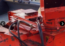
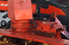
The original chute rotator was seized when I bought my New Idea 7' snowthrower. Normally, I'd just rework the bad bits, but in this case the mechanism had been designed by a disciple of Rube Goldberg and I wasn't about to waste any time "fixing" it. Fortunately, they did one thing "simply", and with 2 bolts and a cut cable clamp, the works were discarded.
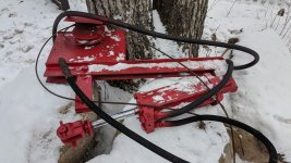
The original design used cable wrapped around a pulley on one end and the chute base on the other. I decided the more elegant solution would be a gear around the chute base, as most walk-behind units use, but I didn't want it worm driven (slow), and I didn't think I'd find any cheap traditional gears this size. So a chain sprocket became the obvious choice as they're cheap, readily available, and would hold up to the task indefinitely with little future maintenance.
Next step was to free the chute base from the chute. Thankfully, someone "farmer welded" the four points attaching the two components, and breaking them free was relatively painless.
Those welds... Ooof!
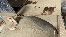
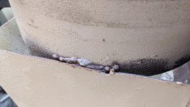
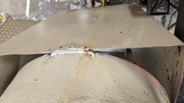
With the base free, I cut off the cable clamp bracket and cleaned up the OD of the chute.
I knew from previous measurements that my gear needed a 12.625" ID hole to fit around the chute base. So I fitted a piece of 2" OD scrap to it's mounting hole, and clamped it in my Super Spacer on my mill.
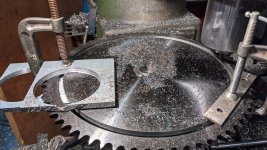
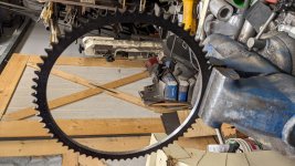
Turns out, I could've stood to have cut the hole a few thou larger, as it took a concerted effort getting the gear around the base, but I did it without heat and no blood loss. :laughing:
After considerable pounding, I managed to get the sprocket down where I wanted it, and then welded it up.
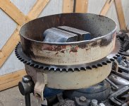
Since I'll be rebuilding the chute when weather improves, I only bolted it back on the base.
I didn't take any picks of the hydraulic motor mounting bracket. It's just heavy angle iron with the appropriate bolt pattern and a 1.75 I.D. center hole to allow the motor to sit flush, then some 1x1 galvanized tubing added.
First mockup of hydraulic motor:
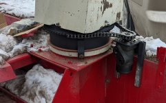
Then it was just a matter of measuring where the chute sprocket was relative to the top of the auger housing, and marking & drilling the holes.
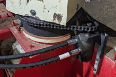
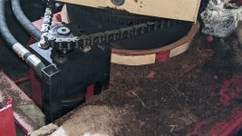
Bolted everything up and added the hoses - she's good to go!

The original design used cable wrapped around a pulley on one end and the chute base on the other. I decided the more elegant solution would be a gear around the chute base, as most walk-behind units use, but I didn't want it worm driven (slow), and I didn't think I'd find any cheap traditional gears this size. So a chain sprocket became the obvious choice as they're cheap, readily available, and would hold up to the task indefinitely with little future maintenance.
Next step was to free the chute base from the chute. Thankfully, someone "farmer welded" the four points attaching the two components, and breaking them free was relatively painless.
Those welds... Ooof!


With the base free, I cut off the cable clamp bracket and cleaned up the OD of the chute.
I knew from previous measurements that my gear needed a 12.625" ID hole to fit around the chute base. So I fitted a piece of 2" OD scrap to it's mounting hole, and clamped it in my Super Spacer on my mill.


Turns out, I could've stood to have cut the hole a few thou larger, as it took a concerted effort getting the gear around the base, but I did it without heat and no blood loss. :laughing:
After considerable pounding, I managed to get the sprocket down where I wanted it, and then welded it up.

Since I'll be rebuilding the chute when weather improves, I only bolted it back on the base.
I didn't take any picks of the hydraulic motor mounting bracket. It's just heavy angle iron with the appropriate bolt pattern and a 1.75 I.D. center hole to allow the motor to sit flush, then some 1x1 galvanized tubing added.
First mockup of hydraulic motor:

Then it was just a matter of measuring where the chute sprocket was relative to the top of the auger housing, and marking & drilling the holes.
Bolted everything up and added the hoses - she's good to go!

