12 volt conversion swap part 1

   / 12 volt conversion swap part 1 #1  

lennyzx11

Veteran Member
Joined
Dec 20, 2015
Messages
1,255
Location
Bennington Vermont
Tractor
Kubota L3301 HST/LA525 & 1964 Ford 2000 gas
After finding out I was going to have to replace the battery in my recently acquired 64 Ford 2000, I decided to go ahead and convert it to 12 volt.

There are numerous ways of doing this.
You can
1. Tweak the 6 volt regulator to have a 12 volt output or replace it with a 12 volt regulator. This only has a weak amp output though so may not keep battery charged. And it’s hard on the 6 volt generator field windings due to more heat from the higher voltage.
2. Farmer conversion. This is just throwing a 12 volt battery in it and recharging it occasionally back in the barn with a charger. Nothing else electrical will work and probably smoke if you turn it on.
Points may suffer burning and pitting rapidly also.
3. Rebuild the 6 volt generator and replace or rebuild the regulator to 12 volt specs. This is the best for a show off restoration and that generator is a lot more water resistant than an open framed alternator. Still will have lower amperage but probably plenty for a tractor’s system
4. And the most popular. Replace with a GM internally regulated alternator. 63 amps right out of the box, less than 100 bucks. And maybe 4 hours to do.
That’s what I did.

MORE COMING
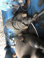
 
   / 12 volt conversion swap part 1 #2  
Thanks for the informative post, food for thought since I have thought of doing the conversion.
 
   / 12 volt conversion swap part 1
  • Thread Starter
#3  
PART 2

I bought a kit. Steiner Tractors, eBay, Yesterday’s tractors, Walt’s, and others offer various versions.

It was pretty straight forward.

Remove the battery and cables for now.
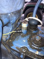
Disconnect the wires to the coil.
Reconnect the distributor wire to the NEGATIVE side of the coil.
Points make a connection to ground. You are switching to a Negative ground.
IMG_1295.jpg

On the opposite side of the engine, remove the wires to the generator and pull the wire going to the coil back from around the front. Whether you replace the harness or not with a new one from the kit, it’s easier to build one and tape it all together off the tractor.

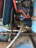
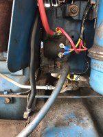
Now we are at the solenoid. Mine is a 4 post. This is NOT the average 4 post ford solenoid you get at NAPA though they look similar. One terminal goes to the starter switch push button on the transmission. Pay attention to which one that is. Mine was on the bottom small terminal as a single wire. (The YELLOW one)
IMG_1298.jpg
The other end of that yellow wire goes to the starter button. That rubber boot will be hard and crack when you try to get it off. It pulls straight back sliding on the wire to reveal the screw terminal connection inside. I’ll edit this when I find a replacement for that boot. IMG_1297.jpg

The POSITIVE battery cable goes on that top large post. I used 24 inch battery cables so I could move the battery out to connect and disconnect the battery terminals easier. Since you are doubling the voltage the current will decrease so you don’t need those huge stiff 6 volt cables any more.

This large top terminal is also where another wire (RED) goes. The other end of that wire is going up under the dash to feed the terminal block and key switch. We’ll get to that shortly.

The other small wire (my original had 2 tied together) on the top small terminal goes to the terminal block under the dash (we’re getting there) IMG_1298.jpg

EDIT My original wiring had two slip on terminals for the two small studs on the solenoid. I had to go find nuts for the ring terminals on the new harness.
#10 -32 fine thread was what I needed. Your mileage may vary.

The Orange and Yellow wires are discussed later in nauseating detail. Stay tuned.

MORE TO COME > Part 3
 
Last edited:
   / 12 volt conversion swap part 1
  • Thread Starter
#4  
Part 3

So where was I ? Oh yeah moving toward the dash. This part kinda sucks since it’s all one handed operation. Looking up through the empty battery box or down through behind the gas tank with the hood open is what you have to work with. Get a good light in there to see.

The old regulator is in there with 3 flat tip screws to remove it. Disconnect all the wires and unfasten the regulator and set it aside. Don’t be scared. And don’t lose the screws. We’re going to need them. We’ll get it all connected back up. (Hopefully)

There is a small terminal board above the regulator. Those two nuts come off too BUT PAY attention to what is connected to which one. Some we will have to put back on.
(I missed the before picture of this. If someone takes one, I’ll add it later.)
So whether you have an ammeter, a voltmeter, or a warning light, you are probably going to have to disconnect that particular thing and you will be ready to remove the harness from the dash. I have a light so I just twisted the socket from behind slightly and pulled the socket bulb and wiring out.
One side of that terminal strip is going to be hot from the battery positive connection on the starter relay. And it will have a wire going TO the key switch. The other wire coming FROM the key switch will go to the other one. This is how the key switch powers everything it should when ON.

MORE MORE MORE COMING
 
   / 12 volt conversion swap part 1 #5  
If you only desired more "oomph" you could have replaced your six volt battery with an eight volt battery and left everything else alone. Yes, eight volt batteries do exist for just that reason.
 
   / 12 volt conversion swap part 1
  • Thread Starter
#6  
If you only desired more "oomph" you could have replaced your six volt battery with an eight volt battery and left everything else alone. Yes, eight volt batteries do exist for just that reason.

Very good point.
In my case, I am replacing lights and work lights. And wanted the full standardized 12 volt system.
And that 8 volt battery was expensive!
 
   / 12 volt conversion swap part 1
  • Thread Starter
#7  
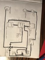
This is what we are working towards.
IMG_1299.jpg

This doesn’t show the accessories like fuel gage, lights, indicator lights, etc. We’ll add them back on later.

More to come. I have to go out and take a few more pictures first.
 
   / 12 volt conversion swap part 1 #8  
Good job on the conversion and thread so far.
Keep it coming!
 
   / 12 volt conversion swap part 1
  • Thread Starter
#9  
Part 4 Under the dash

IMG_1294.jpg

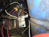
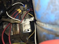
So. Looking at this picture the rectangular white thing is the ballast resistor. This cuts the voltage down from the charging voltage down to an acceptable level to feed the primary side of the coil. (The WHITE Wire)
It is mounted in one of the original holes where the Regulator was with one of the original screws.
White wire goes from positive side of the coil > to one side of the resistor (doesn’t matter which side). Opposite terminal of resistor with short White wire goes up to the Terminal board for the side that only has Power when the Key Switch is ON.

The Terminal board.

One side is Hot from the battery at all times. This is powered from that small wire (Red) that we put on top of the solenoid large terminal with the positive battery cable.
IMG_1298.jpg

That old looking original red wire is going TO the key switch to supply power. That old looking Yellow wire is returning FROM the key switch to power everything on that side when the key is ON.

Next part describes more of the wires.
More to follow.
 
   / 12 volt conversion swap part 1
  • Thread Starter
#10  
Part 5
Safety interlock wiring. And Ammeter.

IMG_1294.jpg

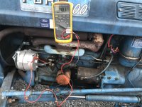
So now looking at the picture, there are two larger gauge RED wires on that left side. One of them is connected to the alternator output terminal. ( over there where I have the red lead of the multimeter attached.) completely off the subject you can see the White wire going to the coil from the ballast resistor routed behind the alternator and around the front of the engine.
(IMG_1289.jpg


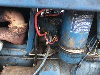
The other one is connected to that large terminal on top of the solenoid with the positive battery cable aforementioned.IMG_1290.jpg

Here is where confusion could come in. That circuit is “supposed” to have the ammeter in it. I don’t have one and actually prefer a voltmeter. I haven’t got it yet.
The proper way for this circuit would be from the battery positive > to large terminal on solenoid top>Red wire to Ammeter terminal. Then from opposite Ammeter terminal that other Red wire goes to that alternator output (batt) terminal on back of alternator.
(Whew, clear as mud.)

You are in effect cutting the wire and inserting the Ammeter in series so it reads amps going to Battery (charging) and amps leaving battery to feed something like starter, lights, etc. (discharging). My kit harness was made for the Ammeter so I used the Terminal board for a convenient place to connect them.
By the way. If you managed to understand all this convoluted information and get it hooked up and the Ammeter is reading opposite of what it should be, just swap the wires on the back of it.

Remember to unhook the battery though! Let’s not make sparks near the gas tank (or anywhere) from that on always Hot wire connected.

And now that orange wire.

It is connected from the key powered on side of the terminal board to the solenoid on one of the small terminals.
It works like this.

When key is ON, power is supplied to one side of the solenoid coil inside the solenoid. But here’s the difference from a regular ford solenoid.
That other small terminal (Yellow) on the solenoid is connected to the starter push button down by the shifter. When the button is pushed, it grounds that side of the coil. That makes an electromagnet pulling the large contact inside the solenoid together to allow power to flow from the positive battery cable on top through to the large terminal on bottom and out to the starter.
Key has to be ON (to supply power).
Shifter in Neutral (to supply ground internally to starter button.
Button pressed to supply Ground to solenoid relay coil inside.
(More than you wanted to know Eh?)

Next will be the mounting of alternator part. Easy stuff.
 

Tractor & Equipment Auctions

2017 Ram 4500 Bucket Truck (A51039)
2017 Ram 4500...
2017 PETERBILT 579 TANDEM AXLE SLEEPER (A51222)
2017 PETERBILT 579...
2019 Generac MLTS-1 2.4kW Towable Light Tower (A49461)
2019 Generac...
2020 KUBOTA RTV X1100C UTV (A51406)
2020 KUBOTA RTV...
2002 Ford F-150 4x4 Ext. Cab Pickup Truck (A50323)
2002 Ford F-150...
2022 LEGUAN 190 SPIDER LIFT (A51242)
2022 LEGUAN 190...
 
Top