12 volt conversion swap part 1

   / 12 volt conversion swap part 1
  • Thread Starter
#11  
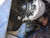
On to the physical mounting. We will come back to the wiring in a bit.

As said before, this was straight forward. Remove the old generator top bracket bolts, bottom bracket bolts and remove the generator. Now remove the brackets from the engine block but keep the bolts.

IMG_1338.jpgIMG_1340.jpgIMG_1337.jpgIMG_1338.jpgIMG_1336.jpg

My kit came with brackets. I have read that you can flip the original generator lower bracket, shim the alternator in line with flat washers and bolt it with a long all thread or stud with nuts.
I didn’t do that.

I have power steering so I had the extra step of removing the power steering belt in order to replace the generator belt with a new slightly longer one for the alternator. I don’t have id numbers for this or length. When I find that info, I’ll add it here.
I pulled one cotter pin and used a pin punch to remove and replace the mounting pin on the power steering pump. IMG_1339.jpg

Fairly easy stuff. I pulled the belt back with my hands “good nuff” and tightened the bolt.

Next. I’ll connect that existing indicator light.
 

Attachments

  • IMG_1335.jpg
    IMG_1335.jpg
    2.9 MB · Views: 116
Last edited:
   / 12 volt conversion swap part 1
  • Thread Starter
#12  
So we didn’t hook up that indicator light. Everything up to now let you get the tractor up and running and charging.

This is the first addition to the basic system.

There are three ways to monitor your fancy new alternator and charging. You can use one, two, or all the ways together. Up to you. I like the voltmeter and idiot light combination myself.

Ammeter.
Voltmeter.
Warning (Idiot) light.

Mine has the light so I wanted it to work. This also is a visual reminder that the key has been left on and the engine is off.

IMG_1349.jpg

So I removed the light socket from the original wiring. One wire had a ring terminal and another wire. We want to save that terminal. It’s gets connected back to the terminal board on the Key switched hot side. (On mine it’s that Right side).
IMG_1347.jpg

So I changed the bulb to a 12 volt (Sylvania 1445) and extended the wire on the opposite light socket wire long enough to reach the alternator. 4 ft was enough. You can scavenge from the old wiring or even the junkyard where you got your alternator if trying to cheap out. We need that terminal plug for the alternator also. It’s all cheap and at the parts store though. ( for a 76-92 GM worked for me) they are pretty standard.

So, from that terminal connection, wire goes up to light socket, bulb, down white wire to terminal 1 of the alternator.
IMG_1343.jpgIMG_1346.jpg

Here’s what we’ve done.
IMG_1352.jpg

A bigger version for this of us that can’t see.IMG_1353.jpg

And here’s the boring details.
Battery power 12 volt flows from the terminal board when key is ON, goes across bulb filament. Bulb lights up.
When engine is cranked, power is also applied from that one wire to the other. They are connected by that light bulb filament. To that Terminal 1 of the alternator. This starts the charging.
Power from the alternator starts flowing Back toward the battery now (14 volts) and meets the power coming from the battery at the light bulb. Since they are now the same. (Remember that big wire on the alternator is feeding charging voltage back to the battery positive?) there is no difference on either wire so the bulb doesn’t shine.

Different possibilities.
Key off, engine off. Light stays off.

Alternator stops charging with engine running. Light comes on.
Key is on but engine not running. Light comes on.
When you shut the engine off, the light will flicker as the charging voltage drops.
If the bulb burns out, the alternator may not charge unless it’s a true “one wire” without revving it up to get the field excited enough to begin.

If we didn’t go through the key switch and light bulb with a just straight wire here? The key switch wouldn’t turn off the engine. The charging voltage would keep backfeeding the coil and the ignition would continue working. The resistance of that bulb gives enough to halt the flow of electricity when the key is off.

Next will be Getting those 6 volts headlights working.
 
Last edited:
   / 12 volt conversion swap part 1
  • Thread Starter
#13  
The Headlights.

So here you have a choice to make.
You can keep the 6 volt light bulbs if they still work by rewiring them into a series circuit.

(I owe you a picture of that. Later edit)

But it’s a pain to try to rewire or cut and splice the wire required that would run from one to another.

And... if one bulb burns out, then both would go out.
Now just stop and imagine you are in a late night drag race against a Ford 8n and just as you reach top speed, your headlights go out ?
Why, you’d have to forfeit the race!

So the better way is to swap over to 12 volt headlights. Mine were 5 3/4 inches in diameter.
That crossed to a Napa 4419N.
They were around 13 bucks apiece.
IMG_1355.jpg

Simple to change the bulb. There’s a tab on the bulb that aligns with a slot in the housing. Get it right or it all won’t go back together.
It doesn’t matter which wire goes where.
IMG_1357.jpg
One point you will figure out. The retaining rings go to a certain side in order to get to the screw head with a screwdriver.

So button up the lights and if your switch is good, you’re set. Mine was rusted out though the original bulbs were good when I initially tested. So I had to change that.

I found a “close nuff” light switch at Oreilly’s auto parts here. (Napa didn’t have one when there), swapped them out old for new and ready for testing.
IMG_1354.jpgIMG_1358.jpg
This is wired to the Key switched side of that terminal board under the dash originally.
Soooo... key has to be ON to turn lights on. Or you can try to test your new headlights by pulling the knob out with Key OFF and watching them shine black for a few minutes while you scratch your head like I did. Then turn key on. Up to you.

Since these bulbs are 35 watts times 2 of them. We have a load of 70 watts on that switch.
Reaching back to old classes( or just Google), we find out that
WATTS = AMPS X VOLTS
70 watts / 12 volts = 5.83 AMPS
You can figure it for the 14 volts when running. I’m tired of doing everything.

So a 10 amp minimum switch rated for more than 12 volts should be a good replacement if you have to replace yours.
Mine’s in the picture below with the new bulbs and one of the old bulbs.IMG_1355.jpg

And the moment of truth..
Ta Daaaa...IMG_1360.jpg

Open items left.
That rear worklight. Do you think mine will buff out?IMG_1361.jpg

Fuel gage. (Measuring stick is working fine)
 
Last edited:

Tractor & Equipment Auctions

2024 New Holland T8.410 MFWD Tractor (A51039)
2024 New Holland...
Informational Lot - Financing (A51039)
Informational Lot...
John Deere 6105E Tractor, 105HP, 4WD, Suspension Seat, A/C, 3 Rear Remotes (A51039)
John Deere 6105E...
2014 MACK CZU613 MID-ROOF SLEEPER (A50854)
2014 MACK CZU613...
VOLVO L45G WHEEL LOADER (A51242)
VOLVO L45G WHEEL...
2019 GENIE Z-45/25XC V2 TELESCOPIC MANLIFT (A51242)
2019 GENIE...
 
Top