2320 and 2520 Hydraulics

   / 2320 and 2520 Hydraulics #11  
PCABE5 said:
2Malamutes,

I was looking today for about an hour thru JD parts and I could not find a diverter valve listed except for the power beyond kit. Do you actually see one on your tractor, if so point me in that direction? I was looking and have not found it yet.

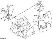
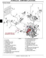
Page 368 of the tech manual has the parts breakdown for the "Divider Valve", and page 352 of the tech manual shows the location of the "Divider Valve" in the stock hydraulic system. It is hard for me to know what you are looking at as I don't have what you are looking at from your dealer, but ask him to pull out his tech manual for the 2320 and look at the pages I've referenced here, and maybe you'll understand where I'm coming from better.

PCABE5 said:
If you look at just what you can pull off line (attached) is a schematic of the steering lines and they do not show a diverter valve in there, nor is it coming off the implement pump (attached).

But if you look at the system as a whole, not just sub assemblies, the diverter valve appears in the schematics as well as the parts breakdowns similar to what you posted.

PCABE5 said:
Now my friend at JD just called me and he said that the 2520 has two Kanzaki 4.9 cu/in implement pumps. So this must be the "two" pumps that is talked about.

But he also said the 2320 implement pump runs the rcv and scv only, he said try driving and steering while loading and you should see no effect on the loader but try and run the 3pt and loader at the same time and one will time out until the other is done, rcv priority over scv.

I don't mean to step on any toes, but it sounds like he doesn't have a real good grasp of what a proportioning valve does. The pump output is fixed at 5.6 GPM, and the proportioning valve ratio is fixed at 60/40, so it doesn't matter if you are using the circuit attached to the 60% side, it has no affect on the 40% side (which is its own open center circuit), which is why what he said is true with respect to steering having no affect on rcv/scv, but the reason is not two pumps, it is because there are two separate open center circuits created by the divider valve (which would emulate a two pump system in some respects so I can understand his explanation, although I think it is wrong.) As the schematic I posted shows, there is no secondary proportioning valve for the rcv/scv which is why they (rcv/scv) would function as he says since they both are open center valves operating within a common open center circuit.

At this point I've done enough research to believe that my tech manual is accurate as it agrees with everything I'm seeing on the tractor. This text is on page 374:

"The hydraulic pump draws hydraulic oil from the transaxle
case, through the filter, then supplies a constant flow of oil
to the divider valve, which diverts 40 percent to the steering
control unit and the remaining 60 percent to the rockshaft
control valve and selective control valve.
Return oil from the steering control unit is routed through
the oil cooler then back to the transaxle case.
"

As well as this text on page 414:

"Pressure oil comes into the steering valve body at the inlet
port from the divider valve. The steering relief valve
regulates the oil pressure to 6,412 +490/-0 kPa (930 +71/-0
psi). The oil then flows through inlet passage to a series of
passages, and slots in the valve body and then on to the oil
cooler. The amount of oil that flows this way varies with the
speed of the turn."

I hope the above is concise enough without seeming like I'm trying to be too matter of fact, I'm just trying to explain to you in technical terms what I am seeing, and why what your dealer is saying just doesn't make sense with anything in the tech manual.
 
Last edited:
   / 2320 and 2520 Hydraulics #12  
2Malamutes said:
"Pressure oil comes into the steering valve body at the inlet
port from the divider valve. The steering relief valve
regulates the oil pressure to 6,412 +490/-0 kPa (930 +71/-0
psi). The oil then flows through inlet passage to a series of
passages, and slots in the valve body and then on to the oil
cooler. The amount of oil that flows this way varies with the
speed of the turn."

This answers every 2305 owners question about where to tie into the hydraulic system for a oil cooler. Thanks for the information.
 
   / 2320 and 2520 Hydraulics
  • Thread Starter
#13  
2Malamutes,

Thanks for the detailed references. I will take this and the schematic to the dealer and have them try to give me some references or pictures of what they are talking about, that is if they can rebute anything that you said.

Does the Divider/Diverter/Proportioning valve in your manual have a part number? Using JD parts online I cannot find one.

Looking at the JD parts they do list the Hydro pump and an Implement pump. I wonder if the later is the divider valve?

I'll post what I find out.
 
   / 2320 and 2520 Hydraulics
  • Thread Starter
#14  
Ok, I am convinced that you are right and that the tech manual is accurate.

This is what I got today:

The implement pump supplies fluid to the housing where the rock shaft mounts thru. From this housing the fluid goes out two different fittings, one to the power steering and one to the scv. The diverter must be internal to the housing as I do not see anything externally. To get a really good view of this you have to remove the seat and plastic shroud as it is all hidden under there. The attached image shows the pump and the housing that I am talking about.

Now my friend was either confused, telling me a lie or confusing the 2320 with the 2520. The 2520 has a implement pump mounted on or in the front cover of the main pump housing and this supplies the power steering. Another implement pump supplies the same rock shaft housing where it supplies the rcv and scv.

From my previous post discriptions of what I was told it seems that I was explaining a 2520 and not the 2320 so the diagram and info that he was giving me was the wrong tractor. I would like to give him the benefit of the doubt but the service manager today took the time and pulled both tractor books.

Also to note is the last post that 2Malamutes posted. This was a very through explaination and documented with page numbers and a complete diagram of the hydraulic system. With this kind of information I was ready to go to the dealer and also with this type of information we all can trust that it is accurate and not just an idea of how it works. My hats of to you for being so through with your posts. Hopefully I was clear enough in my explaination.

Hopefully no one took offense by my insistance, but I just wanted to know one way or the other. Now I know and so should anyone else that has this question.
 

Attachments

  • Transmission Suction Line and Implement Pump2.jpg
    Transmission Suction Line and Implement Pump2.jpg
    51.6 KB · Views: 390
   / 2320 and 2520 Hydraulics #15  
PCABE5 said:
2Malamutes,

Thanks for the detailed references. I will take this and the schematic to the dealer and have them try to give me some references or pictures of what they are talking about, that is if they can rebute anything that you said.

It will be interesting to hear what they have to say, based on what they've already told you they "know".

I've attached the most illustrative schematic I can find, which clears up any doubts I had since I took this out and traced lines on my 2320 and it looks exactly like this schematic from my tech manual. Big arrow (and "Q") point to Divider Valve, and the "Steering Control Unit Supply Line" (V) comes out of the Divider Valve just as the schematic I posted in an earlier thread shows. I've added some poorly drawn red arrows that show direction of flow, which is why I questioned your earlier post stating the steering supply line originates in the cooling circuit, since as you can see the cooling comes into play on the sump side of the steering circuit, which follows with typical hydraulic systems (return side cooling).

EDIT* I was composing this as you were posting your last response, thanks for the follow-up.
 

Attachments

  • HSystem.jpg
    HSystem.jpg
    134.4 KB · Views: 407
   / 2320 and 2520 Hydraulics #16  
As far as what you gain with the 2520 hydraulics: while looking up some info on JD's site on the 200CX loader, I found some full spec sheets on the 200CX on various tractors. Weights, heights, etc. were almost identical for the 2520 and 2320 but the following reflects the 50% greater pump output for implements, and is basically that same gain in terms of times.

2320 Cycle Times:

Loader raise, seconds 4.73
Loader lower, seconds 2.88
Bucket dump, seconds 4.73
Bucket rollback, seconds 2.88

2520 Cycle Times:

Loader raise, seconds 3.19
Loader lower, seconds 1.95
Bucket dump, seconds 3.19
Bucket rollback, seconds 1.95
 
   / 2320 and 2520 Hydraulics #17  
Interesting and informative read, I had assumed that Deere was using a two section hydraulic gear pump. Guess I was wrong


Steve
 
 
Top