TY395 Valve clearance adjustment and head bolt re-torque procedure.
Click on the pictures below to see a full size picture with details.
Disconnect the de-compression rod at back of valve cover.
Do this by removing the cotter pin and sliding out the pin.
Remove the three acorn nuts, washers and rubber seals on top of valve cover.
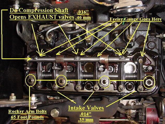
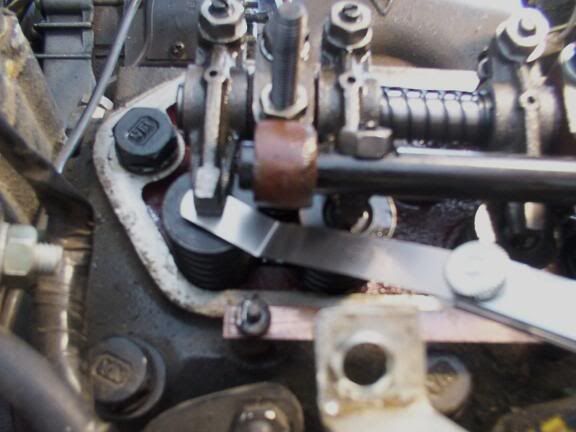
Remove the valve cover to expose the rocker arms, adjusters, and head bolts.
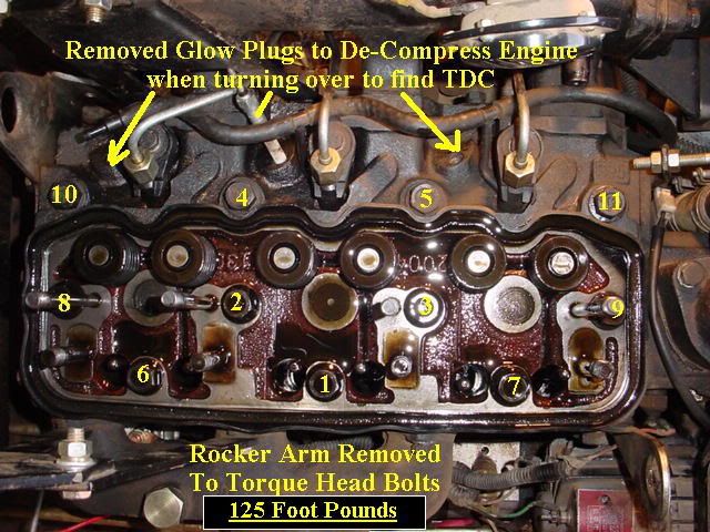
Remove the 4 rocker arm nuts by loosening each one a little at a time as the rocker arm is under extreme pressure by the valve springs. Once the 4 nuts are removed lift off the rocker arm assembly and set it aside on a clean surface.
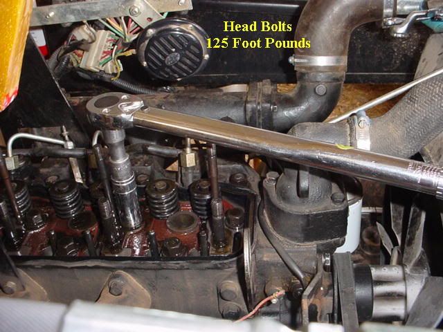
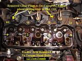
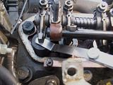
Re-torque the head bolts to your engines specs ~ 125 foot pounds. Using the pattern as indicated in the photo.
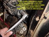
Re-install the rocker arm assembly tightening each nut a little at a time to re-compress the springs and so that is goes straight down evenly and does not bind. Tighten the rocker arm nuts to 65 foot pounds.

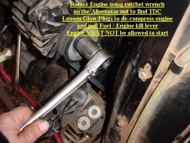
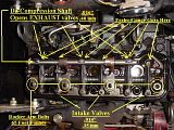
In order to adjust the valve clearance you must find Top Dead Center for each cylinder one at a time. You must keep the engine from starting or even trying to start –
Turn off Fuel at fuel bowl, Pull and tie back the fuel cut off, Place transmission in neutral and set the parking brake. If you so desire you can also loosen the glow plugs to de-compress the engine doing this makes it much easier to rotate the engine.
Rotate Engine clockwise using ratchet wrench on the Alternator nut to find TDC.
Start with the number one cylinder - the one closest to the radiator. Rotate the engine clockwise while observing the intake valve, when the valve opens then closes all the way you are now at Bottom dead center for that cylinder. Mark the crank shaft pulley with a piece of tape then rotate an additional 180 degrees this will be very near top dead center on the compression stroke. At this point you can now set the intake and exhaust valve clearance for the number one cylinder. Check gap with feeler gauge between rocker and the top of the valve. To adjust loosen the locking nut on opposite side and with a screwdriver turn in or out the adjuster to achieve the proper valve clearance. Once proper clearance is obtained hold the adjusting screw with a screwdriver while tightening the locking nut re check clearance and repeat as needed until the clearance is correct and the locking nut is tight. Now repeat the entire process for the number 2 and number 3 cylinders making sure to find top dead center on the compression stroke for each cylinder.
Once complete replace the valve cover making sure the de-compression assembly fits properly into the decompression rod on the rocker arm assemble. Reattach the decompression rod on the outside of the valve cover and replace the cotter pin. Check for proper decompression lever operation then replace the three rubber seals, washers and acorn nuts on top of the valve cover.