Cidertom
Gold Member
- Joined
- Dec 14, 2005
- Messages
- 478
- Location
- Benton Co Oregon
- Tractor
- JD 4520, 2305 Aktive snow-trac ST4
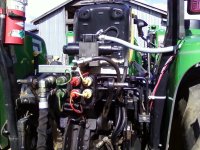
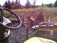
After several requests for details and pix, here is my modification to add an electric valve as a 6th scv to my 4520 to enable a hand control. Basic concept: Using the power beyond I placed a solenoid valve in line to drive the 4-in-1 with a hand control on the main scv joystick.
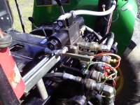
I used a larger than needed valve to limit the pressure loss through the valve. It is a DO5 series with two solenoids providing push/pull/hold. The hold position links the P and T ports. The control handle is from Deere and is a part for the 110 TLB (pricey). The handle drives two relays, which fires the control valve.
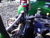
Installing the valve: Made mount with strut. It would be prettier with a custom made weldment, but... The Mount is held up with 1" aluminum pipe segments 5" long and a fitting bolted to the connector mounts. I measured and cut the power beyond hydraulic line from the scv block, then brazed a fitting on. Wouldn't do it again. If I were doing it again, I would use a 5/8" hose with #10 JIC ends (adapt as required) . Remove the short end by removing the snapring from the coupler mount. Remove the steel tube and FF to O ring adapter. Install a hose from that coupler to the T port on the valve. Reinstall the snapring. Using a sweep elbow and a 90 deg hook the power beyond line to the P port. Currently I am using the couplers for the 4-in-1 lines. The 90 fittings on the end of the hoses are welded and I didn't want to fish them out to have them re-coupled (will happen this summer).
I replaced the short cord from the TLB handle with a longer one. I wouldn't do that unless you are used to circuit board re-work with thick conformal coatings. Instead just do a neat job of splicing an extension or find the matching connectors. Make certain you place snubber diodes on both the relays and the solenoids (total of 4) . I placed the relays in the RH fender compartment. I pulled a #10 wire with a 30 amp fuse from the battery terminal on the starter to the fender for this project and future lighting circuits.
It is not as smooth as a manual or porportional valve. For me it works OK. I have considered a restrictor or needle valve in line. The "book" would have a relief valve between the A-B ports.
Not suggesting this modification, if you do it: It's all on you.
Have fun
CT
I used a larger than needed valve to limit the pressure loss through the valve. It is a DO5 series with two solenoids providing push/pull/hold. The hold position links the P and T ports. The control handle is from Deere and is a part for the 110 TLB (pricey). The handle drives two relays, which fires the control valve.
Installing the valve: Made mount with strut. It would be prettier with a custom made weldment, but... The Mount is held up with 1" aluminum pipe segments 5" long and a fitting bolted to the connector mounts. I measured and cut the power beyond hydraulic line from the scv block, then brazed a fitting on. Wouldn't do it again. If I were doing it again, I would use a 5/8" hose with #10 JIC ends (adapt as required) . Remove the short end by removing the snapring from the coupler mount. Remove the steel tube and FF to O ring adapter. Install a hose from that coupler to the T port on the valve. Reinstall the snapring. Using a sweep elbow and a 90 deg hook the power beyond line to the P port. Currently I am using the couplers for the 4-in-1 lines. The 90 fittings on the end of the hoses are welded and I didn't want to fish them out to have them re-coupled (will happen this summer).
I replaced the short cord from the TLB handle with a longer one. I wouldn't do that unless you are used to circuit board re-work with thick conformal coatings. Instead just do a neat job of splicing an extension or find the matching connectors. Make certain you place snubber diodes on both the relays and the solenoids (total of 4) . I placed the relays in the RH fender compartment. I pulled a #10 wire with a 30 amp fuse from the battery terminal on the starter to the fender for this project and future lighting circuits.
It is not as smooth as a manual or porportional valve. For me it works OK. I have considered a restrictor or needle valve in line. The "book" would have a relief valve between the A-B ports.
Not suggesting this modification, if you do it: It's all on you.
Have fun
CT
")
