8B Backhoe On A 4200?

   / 8B Backhoe On A 4200?
  • Thread Starter
#11  
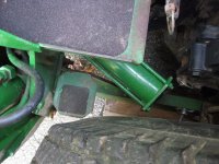
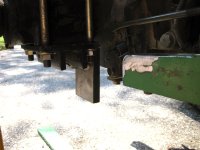
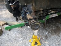
With the tractor only 3.5 inches off the ground the seat already clears. Thats great news as it means one less thing to worry about.

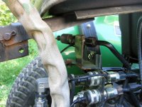
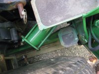
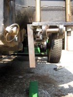
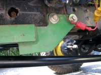
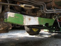
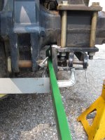
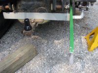
And although I didn't get exactly centered during my trial fit, you can see the tires and PTO cover clearances. The 8B has the pivot cylinders sticking out behind the operator platform. Probably because its so far away from the 970 anyway. But I can get it really close to the back of the 4200. More great news.
 

Attachments

  • seatclearance1.jpg
    seatclearance1.jpg
    201.9 KB · Views: 248
  • tireclearance1.jpg
    tireclearance1.jpg
    213.8 KB · Views: 232
  • tireclearance2.jpg
    tireclearance2.jpg
    214.5 KB · Views: 212
   / 8B Backhoe On A 4200?
  • Thread Starter
#12  
I've also figured out by now that there is no way to reuse the original mounting design. The cam locks would be three inches off the ground if I did. The problem is that the subframe is too narrow to fit between the ROPS bracket and the rear housing. So it would have to go under the rear housing. And thats just unacceptable.

So at this point I'm copying dfkrug's design very closely. First the extension needs to be added to the bottom ROPS bracket. Mine came out embarrassingly crooked. I swear I measured it and thought it looked straight in the vice! It'll still work though.
 

Attachments

  • ropsbracket1.jpg
    ropsbracket1.jpg
    192.9 KB · Views: 264
  • ropsbracket2.jpg
    ropsbracket2.jpg
    153.7 KB · Views: 214
   / 8B Backhoe On A 4200?
  • Thread Starter
#13  
On to the front frame reinforcement..... this was very fortuitous.... the original frame reinforcement brackets from the 970 have the same hole spacing as the holes in the front of the tractor. So a 1985 design has made it all the way to 2003 without even being used!

The bracket is a little short but we'll figure that out. First I cut off the cam lock and the rear mounting plate. You can see how it looked originally in the last picture of the first post.
 

Attachments

  • framesupport4.jpg
    framesupport4.jpg
    186.5 KB · Views: 235
  • framesupport3.jpg
    framesupport3.jpg
    191.8 KB · Views: 224
  • framesupport2.jpg
    framesupport2.jpg
    224.6 KB · Views: 176
  • framesupport1.jpg
    framesupport1.jpg
    223.1 KB · Views: 198
   / 8B Backhoe On A 4200?
  • Thread Starter
#14  
While engineering the extension to the ROPS bracket I figured out I needed a flat spot at the back of the front bracket to have a good spot to weld on. Out comes the grinder. The neighbor offered his band saw but it would have taken longer to get it than it was to grind it.

You can see how the extension will attach. And you can see where I'm reusing the metal from the top support I cut apart earlier. I could make this joint much stronger with extra plate welded in. And I will add some triangular reinforcement brackets. But......

.....I decided to make this the engineered weak point in the subframe. If so much force gets transferred this far that something is going to break, I'd rather it was my subframe than the tractor's transmission tunnel.

Whether I will reconsider the designed strength of this joint at some point is still up for debate.
 

Attachments

  • framesupport5.jpg
    framesupport5.jpg
    183 KB · Views: 164
  • framesupport6.jpg
    framesupport6.jpg
    175.2 KB · Views: 156
  • rearsupport3.jpg
    rearsupport3.jpg
    166.6 KB · Views: 181
  • rearsupport4.jpg
    rearsupport4.jpg
    164.6 KB · Views: 186
   / 8B Backhoe On A 4200?
  • Thread Starter
#15  
And some more pictures of the the brackets and how they'll look. The end of the extension will have the backhoe mounted to it. I'm going to weld the bar to the original subframe after some careful measurement. I haven't fully engineered everything here yet but I do know I will have to cross brace a good bit to handle any twisting forces.

You can also see where I'm going to use the drawbar as a support. The drawbar can handle 1500lbs of weight. So it might as well be part of the weight distribution design. I think it will make it easier to mount and dismount the subframe too because it won't just drop when you unbolt it from the ROPS bracket.

I've currently tack welded all that together. Its at the neighbor's shop so I can drill two holes. As soon as thats done I'm putting it all back together and repeating all this on the other side. Then onto the back part. If it isn't raining tomorrow I'll make some good progress on it.
 

Attachments

  • rearsupport1.jpg
    rearsupport1.jpg
    278.4 KB · Views: 208
  • rearsupport2.jpg
    rearsupport2.jpg
    215.1 KB · Views: 195
  • drawbarsupport1.jpg
    drawbarsupport1.jpg
    285.8 KB · Views: 183
Last edited:
   / 8B Backhoe On A 4200?
  • Thread Starter
#16  
As for my hydraulic issues, I guess I will get to them later. AKFish, I was thinking more about it, and dfkrug gave me some ideas, and I don't think the valve works quite like we were saying. If I'm providing less gpms, it'll just move slower. The valve doesn't care about its fill rate. It'll send fluid to the work ports at the same rate as it receives it. Its not cavitating because of a lack of fluid. Know what I mean? So something else is the problem. If I have to rebuild the valve or something.... thats going to happen after the subframe is built.
 
   / 8B Backhoe On A 4200?
  • Thread Starter
#17  
AKfish, I have to apologize. I totally misread your post. I just read it again (for the fourth time) and realized I read the opposite of what you said. So yes, there has to be some kind of restriction. Going about finding it is going to be a pain.
 
   / 8B Backhoe On A 4200? #19  
First the extension needs to be added to the bottom ROPS bracket. Mine came out embarrassingly crooked. I swear I measured it and thought it looked straight in the vice!

When I first saw your photo, I thought you were trying to weld this up
on the tractor. You are using some pretty thick steel there....looks like
maybe 3/4"?

I used a welded-on brace to keep this weldment perpendicular. I guess
you did not. I knew that heat distortion was going to have to be
managed.

Question: do the turf wheels have a different spacing if you flip them
around? Glad to see you can get the hoe in really close.

As for the hyd issue, that can be explored when you get a pressure
guage setup so you can dynamically monitor what is happening.

There is certainly nothing wrong with providing connections to your
draw bar bracket, as long as that does not decrease your ground
clearance. Note that if you have a cross brace here, you will not have
the tiny bit of flex that you may need to bolt up to the above weldments.
Clearance will have to be about 0. Something to consider.
 
   / 8B Backhoe On A 4200?
  • Thread Starter
#20  
Yes, that piece welded to the ROPS bracket is 3/4". I'm just using what I have. No point in spending yet more money and having this piece lay around for another four years.

I used a welded-on brace to keep this weldment perpendicular. I guess you did not. I knew that heat distortion was going to have to be managed.
Just learned something.... weld-on brace. I did manage heat distortion. I did think of that. If you take a square to each part of the new bracket, each face is perfectly flat. So I got that right. Its my lame redneck-engineered jig that failed me. I'm gonna fix it on the backend. I got some really good penetrating welds into it and I didn't want to redo it and possibly weaken it.

Question: do the turf wheels have a different spacing if you flip them around? Glad to see you can get the hoe in really close
Yes, 1.5" per side. Just figured that out the other week while I had the wheels off to air them up. The turfs on a 43/4400 are taller but narrower. I don't remember what Roy and I gained when we flipped his. I believe it was more than 3 total inches but I'm not sure. Roy?

And yeah, I was surprised how close the hoe came in. I could take off the bottom corner of the PTO shield and the hoe's lower steps and come in another 1-2 inches. But then the stabilizers would 1/2" or less from touching the tires. Thats probably too close, yes?

Note that if you have a cross brace here, you will not have the tiny bit of flex that you may need to bolt up to the above weldments. Clearance will have to be about 0. Something to consider.
I think I have this covered. But you maybe right. We'll see when I get it together. I may change it to a bolt together design if necessary. I'd really like to distribute the weight here though. I don't like how all the weight is on the ROPS welds otherwise.

What do you think of adding a cross brace at the front of the frame that gets screwed to the bottom of the tunnel? There are two tapped holes there too. My initial concern is that it will be near impossible to remove this thing but my major concern is weight distribution.
 

Tractor & Equipment Auctions

Willmar 4300 Wrangler Loader (A52128)
Willmar 4300...
2018 GENIE GTH-5519 TELESCOPIC FORKLIFT (A51242)
2018 GENIE...
CAT 573 FELLER BUNCHER (A51242)
CAT 573 FELLER...
90018 (A48082)
90018 (A48082)
2004 Sterling L8500 4,000 Gallon T/A Water Truck (A50323)
2004 Sterling...
2019 CHEVY 5500 CAB CHASSIS (A50505)
2019 CHEVY 5500...
 
Top