Alternator wiring....

/ Alternator wiring.... #1  

StevenPaul

Silver Member
Joined
Sep 9, 2005
Messages
133
Location
Anderson County, SC
Tractor
John Deere 2010 (Kranky), JD 4500
Hello All!

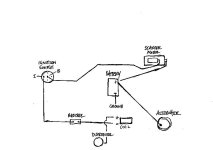
Is there anybody out there that can post/reply in here or send me an email (Im4theSon@aol.com) for a JD 2010 wiring diagram. I've got the service and parts manuals but it doesn't give a wiring diagram for an alternator system. We've removed the voltage regulator and any excess wiring. We've got a negative ground system with an alternator, coil, starter motor, battery, and ignition switch. Currently there is an amp meter gauge installed. We can get it running but the coil gets extremely hot and the ignition switch little coil thing on the back starts to heat up and smoke. We think we have it wired wrong, yet it somehow sometimes works. Obviously I'm not an electrical engineer so any replies, please be as simple as possible. At first it acts like it wants to start up then the battery dies and we have to end up usually jump startin it. It's like something is constantly draining the battery. Any and all help would be greatly appreciated.

thanks!
Steve
Anderson County, SC
 
/ Alternator wiring.... #2  
Very difficult to advise on electrical problems without seeing the system and/or running tests but if you've removed the voltage regulator from the system, you could possibly have upwards of 19 or 20 volts from your altenator and quite a few amps!! If you're not going to use all the original electrical system, you need to install an altenator that has an internal regulator and 1-wire hook-up (internally excited) - they can be had for under $40. The 1 wire is usually a 10-ga. wire to the positive battery post or where the positive cable hooks to your starter. Your charging voltage should run between about 13.4 to 14.8 VDC. Your ignition coil has to be resisted for a point-style system, whether internally or externally. The simplest is the internal and you can hook system voltage right to it from your ignition switch. Point-type coils are supposed to operate at approx. 9 or 10 VDC, except for initial starting, so you have to add a ballast resistor if using an externally resisted coil. Running higher voltage will cause points to burn/pit very quickly and eventually burn-up the coil. Make sure you have good grounds everywhere too. Maybe this helps a little - good luck.
 
/ Alternator wiring....
  • Thread Starter
#3  
I did forget to mention, that we do have a 1 wire alternator. As for the internal/external coil stuff, not sure about that. All I know is that it's a pretty new 12V coil and it does have a wire going to the distributor. I've got 4 hook ups from the ignition switch, BAT, IGN, SOL, & ACC. I'm needing to know where do the all the wires go from the ignition.

thanks again for the help!
Steve
Anderson County
 
/ Alternator wiring.... #4  
Does the coil have an internal resistor ? Or does it use an external resistor ? Basically all coils are 6V , they either use an internal or external resistor to limit current. some systems have the resistor out of the circuit for starting and the coil in circuit for running. Some have coil in the circuit all the time.

I am assuming that this tractor has a gas engine.....

Ben
 
/ Alternator wiring....
  • Thread Starter
#5  
ok, talk about feeling like an idiot, I just went out and looked (in the rain) and it's 12V coil and it says, external resistor required. Sheeeesh, what a man I am! hahaha! reading the directions after installation. Ok, so what do I do after getting the external resistor? And where do I go with all the other wires from the ignition switch?

thanks again!
Steve
 
/ Alternator wiring.... #6  
The resistor will go in series in the positive lead going to the ignitin coil. Prob the IGN term on your switch. I don't really know in your situation where the rest of the wires go, sorry. here are some ideas.

ACC = to lights and such
BAT= to battery
Ign = to coil
I have run the little lead out of some one wire alternators to the IGN leas as well, so that the alt is cut off when the switch is off.

Ben
 
/ Alternator wiring....
  • Thread Starter
#7  
here's my ignition switch, and I'm an idiot twice today, trying to break my record of being one all day I guess, haha! Anyways, the letters on it are I(ignition), B(battery), L(2 prongs = lights?), S(?), & F(?). The other identification I previously posted was for an ignition switch we used in place of the original one for a while. Does this help anybody with being able to tell me where the wires should go?
 

Attachments

  • 749956-M4100012.JPG
    749956-M4100012.JPG
    14.6 KB · Views: 273
/ Alternator wiring.... #8  
L is probably lights.
S might be starter, wires to starter solenoid.
F hmmm could be field for the alternator or maybe fuel shutoff, not sure at all on that one.

Ben
 
/ Alternator wiring....
  • Thread Starter
#10  
thanks y'all, just went out and bought the resistor for the coil, "F" for fuel gauge makes sense, but I don't have one. Now all I have to do figure it all out. If y'all think of anything else, let me know. I'm kinda pieceing this thing together with your help and what I'm finding on the internet.

Steve
 
/ Alternator wiring....
  • Thread Starter
#11  
ok, this is what I've configured so far; for a negative ground system, see also the attachment,

battery cable to (-) ground
battery cable (+) to starter motor, then
one wire from the alternator to (+) battery post,
coil wire (-) to coil resistor to I(ignition) prong on starter switch, and then finally, a wire from the starter motor to the B(battery) prong on the starter switch. Does this sound right?

All the other electrical will come later, the lights, gauges, etc.

and F is for fuel gauge

thanks again for the help,
Steve
 

Attachments

  • 750033-2010 alternator wiring.jpg
    750033-2010 alternator wiring.jpg
    28.1 KB · Views: 1,491
/ Alternator wiring.... #12  
Steve,
From the ignition switch to the starter I have a relay that I think is designed to take the high current switching that may help with protecting the solenoid contacts. Am not positive if that is what it is for but think that it may be. Also not sure if it is necessary or how much it helps.
Sounds like you have pretty much got the wiring figured out. I am going to print out your diagram and check it against my 2010 wiring. It may be tomorrow before I get back to you.
Farwell
 
/ Alternator wiring.... #13  
The engine starts on 12 volts and runs on 6 volts through the ballast resistor. To get 12 volts to the coil for starting, you run a wire from the starter solenoid to the positive terminal on the ignition coil. This wire should only be energized when the ignition switch is in the start position and the starter is cranking. When the ignition switch returns to the run position, then this wire will not have any current flowing to the coil and the coil will only be supplied with power through the ballast resistor. Using a test light, check the terminals on the solenoid to establish which one to use. It should only have power when the starter is cranking. The reason for this is the ignition points cannot handle the higher voltage and amperage. I suggest that you check your points to make sure that they haven't been damaged from your prior use without the resistor. The ballast resistor is usually fed through the ignition switch so when the ignition is turned off, there is no current flowing to the coil. The ignition points complete the circuit for the ignition coil and turn the power on and off to the coil. When the power to the coil is turned off, the high voltage that is built up in the coil is directed to the distributor and then to each spark plug in turn. If power is left on to the coil when the engine isn't running it will drain the battery

The "F" terminal on the ignition switch is a hot lead to the field terminal of the voltage regulator. On a single wire alternator system, this terminal isn't used. The "F" terminal originally went to the field terminal of the voltage regulator.
 
/ Alternator wiring....
  • Thread Starter
#14  
thanks Farwell, I look forward to your findings.

And HonourMe, I will check the points and do the test light thing. I think I understand what you mean by the test. Is there any particular test light I should be using?

Steve
 
/ Alternator wiring.... #15  
The test light should be one that has a 12 volt bulb and a tip that you place on the wire that you are checking. The other connection is a wire to ground. DO NOT use a battery operated test light. Those are used for another purpose. Most automotive testing is done with the type that I have described. You can purchase it at a auto parts store for a few dollars or buy a super duper one from Snap-On for about $25. Both will work just as well, and the only difference is in the quality of the parts. I don't believe that you need the fanciest one available. You can actually make one out of a 12 volt bulb and pigtail socket. Just extend the wires and put two clips on the ends of the wires. Clip one wire to ground and use the other to clip onto the terminal or to just touch the terminal. If you go looking for on in the auto department, they are commonly known as "Continuity Tester".
 
/ Alternator wiring.... #16  
You've got your coil leads reversed - the negative terminal from the coil goes to the distributor - the points make the ground. The Positive terminal on the coil should be getting the power from the ignition switch via the ballast resistor as well as the wire from the starter solenoid or relay that has the 12v when starter is engaged. And yes, the "F" terminal stands for field - leave it empty with your current altenator. The "ign" terminal usually will feed other items that you want power to with the key on, not just the ignition system, be sure these items are fused and have your fuses as close to the switch as possible to protect as much of the wiring as possible - a simple inline fuseholder will work.
 
/ Alternator wiring....
  • Thread Starter
#17  
ok, stuck again, back to square one, and all that "in a day's work and accomplish nothing" stuff. I tried wiring the tractor as I posted and as a few of you have suggested and zip, nada, zero. I did get smoke and a really nice orange glow from the resistor though. The little resistor lookin thing on the ignition switch started smokin too. I tried several combinations and after it all, we end up with where we began, wired the way we had and having to jump start it every time and then there's the hydraulic fluid comin out the steering wheel when it gets cranked up and runnin. So all was not lost, found another problem, had my dog growl at me, and scared my son with an occasional turn of the switch while he was doing the test light thing. Funny, I don't remember being able to jump that high when I was 16. What I think I might do is take some pictures and post them and see if any of you can tell me what I'm doing or wiring wrong. All I want for christmas is for my tractor to start with a key. And as you can tell I'm probably going to be pickin y'alls brains on some hydraulic questions... but that's another day.
 
/ Alternator wiring.... #18  
Don't know what type of ignition switch you are using, but that might be part of the problem. Go to the auto parts store and buy a generic replacement ignition switch. A good choice is a Cole Hersee brand switch. They have a website with wiring schematics that will help you get it right the first time. If you overheated the ballast resistor, you might have burned it out. It shouldn't get that hot. It also might be wrong for the application. A good auto parts counter man should be able to help you with this.
 
/ Alternator wiring.... #19  
Wow.. not sure what happened.. but don't think you actually got it wired as directed.

Break down the circuits individually. First ignition.. + to switch.. then from ignition side of switch to ballast resistor.. then from there to coil + from coil - to distrib.

If your ballast resistor died, try crossing an 8ne10306 it is a generic 12to6v converting resistor used on many fords.

After that.. tackly the starter circuit.. it will be the momentary contact on the ig nition switch, to the solenoid.

Then tackle charge cuircuit.. etc.

Soundguy
 
/ Alternator wiring....
  • Thread Starter
#20  
Well, I think we're narrowing it down. Bought a new switch (generic) and a new internal resistor coil and things looked and sounded better but still having to jump start. We checked the alternator by using that test light. We took the wire off from the alternator to the battery and started the motor and then put the test light clip to ground and then the end of the test light pointer to where the wire goes on alternator and no light. Is this a correct way for testing an alternator? Also in doing some research, I found that I need to check to see if I have a negative ground alternator, how do I do this? And seems like I read somewhere where the alternator has to have a minimum of 1200 rpms to kick in or something, is this true? Can I put a tachometer or some kind of rpm gauge on the tractor? All in all, things are looking better though, thanks again for y'alls help.

Steve
 

Marketplace Items

2017 FREIGHTLINER CASCADIA SLEEPER (A59905)
2017 FREIGHTLINER...
17501-FL (A56857)
17501-FL (A56857)
New Holland T2420 (A53317)
New Holland T2420...
(APPROX. 640BF) 1X6X6-16 WHITE PINE TONGUE & GROOV (A52706)
(APPROX. 640BF)...
2016 Lincoln Navigator SUV (A59231)
2016 Lincoln...
Bobcat T590 (A60462)
 
Top