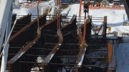
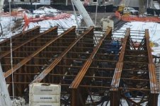
Thank you to all for your comments so far -- exactly why I joined!
I might not have been as clear as I should have been....this is not a "DIY by guessing" kind of job. I will certainly be having a local engineer do the planning and final calculations and tell me what I need -- but I was trying to do more of the design work myself and hopefully come up with a feasible idea instead of spending the engineer's time on design. I had downloaded BeamBoy and must have been doing something wrong because I wasn't having much luck in getting a deflection and/or weight rating, so I appreciate the calculation on my behalf. And "pier" was a poor choice of words, since I know that the abutments on which these beams will rest are going to have to be pretty heavy duty and will take a lot of cement to form.
I appreciate the comments and ideas -- always willing to hear more. I will continue to update as we get further along in the planning process.
Chris
How far were you able to get with beamboy? Were you able to get the beam with supports and load drawn? I'll walk you through everything in any case.
1. when you open the program, you are prompted to choose a beam length. So I'll choose 35'
2. Now you have to select the features. At the top, second tab is features, then add feature, then add support. You need 2 supports. One at 0' from left edge, one at 36' from left edge.
3. Now add the load. this is also under features tab. You can have a point load, or distributed load. I choose point load of 100,000# at 18'. So a whole lot of weight, right at mid span.

4. Now select the I-beam properties you will be using. Beamboy has alot of info saved on common stuff. So go to the beam tab at the top, and select properties. Here you can manually input information, or click "choose" to select a beam they have in their system. After clicking "choose", select the W33x118 beam you have, then select "use x-x values". The y-y specs would be if you had the beam laying on its side.

Now that the beam is choosen, the final step is to calculate the stress and deflection. It is under the tab "calculate", then calculate stress and deflection. What pops up should look like this:
Beam deflection of 0.95" And a bending stress of 30,000psi. Since the steel is typically A-36 Which is 36000psi steel, you are under on stress, and deflection is usually not to exceed L/360. Where the length in inches is 432. So 432/360 is 1.2" max allowable deflection.
The beams are NOT going to be the weakest link. Using more realistic loading, lets say a set of tandems from an 80,000# dump truck or concrete truck. For a 36' bridge, the front axle is gonna be pretty muck off the bridge before the rears go on. So lets say this truck has 60k over the rear tandems. Which is 30k per axle, and 15k per side per axle. Assuming the axles are 4' apart, lets draw up a beam with two 15k point loads each 2' off center
That represents a more realistic loading. Here is what the stress and deflection look like
1/4" deflection when 1.2" is allowable. And only 8000psi bending stresses on 36ksi steel. Yea, the beams are fine. And like I said if you can work out the decking, I would not use all 4 beams. You can probably sell 2 of the beams to pay for the rest of the project.
ANd you can also use beamboy for wood beams too just so you know. When selecting beam properties, instead of hitting choose, select calculate. Input the wood dimensions and it will give you the i4 and distance to farthest fiber numbers. Then you have to change the modulus of elasticity to match whatever the lumber you are using. Steel is 30million. Wood is usually around 1 million. If you dont change that, and input your 4x10 dimensions, it will give a result as if it were 4x10 solid steel. You also have to know the max stress allowed in the wood. Where A36 steel is 36ksi, for wood the Fb is lower. usually between 500-1000psi for graded lumber. And up to and over 2k for MSR and engineered lumber