Building Hydraulic Tank

   / Building Hydraulic Tank #1  

Jorville

Bronze Member
Joined
Apr 14, 2012
Messages
90
Location
Burnsville, MN.
Tractor
WD Allis, Case 580 CK, HD5 Allis crawler, Bantam Koehring track hoe,
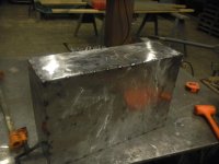
I needed a hydraulic tank of a specific size so I built one for my hydraulic unit. The tank completely filled will hold 17 gallons, I keep it at 15 gallons. The tank holds a little over a gallon per inch. The first picture shows another tank where the pieces were cut out of. That truck that tank was on was scrapped out a year earlier. It would have been nice to have had the pieces sheared from new sheet metal. The pieces would have been perfectly square then. They are pretty close now. The sheet metal is ten gauge.

View attachment 442196


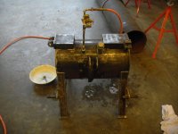
Tank with two sides and bottom with baffle welded together. The baffle is so the return oil can not just return on one end of the tank and go pretty much directly to the supply port.

412.jpg


tank tacked together without last side

414.jpg


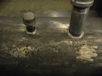
Tank completely tacked together so corner welds can be made without filler rod. Tank was oxygen/acetylene gas welded together. The arc weld tacks were burnt into the weld as the corners were fused together without filler rod. Had to add a little filler rod once in a while when the bottom of corner had a little gap. After tank was completely welded together I had to vacuum out the tank. Tank had weld splatter inside it. The inlet and outlet ports were welded with 3/32 7018.

416.jpg


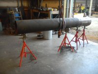
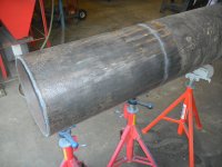
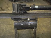
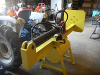
Tank on the wood splitter. I completely rebuilt the Hydraulic unit. Another engine, the old engine was crank start, sure is nice to have a starter motor. New hydraulic pump, all new hoses. The only thing from the old machine was the frame and cylinder and Valve and the parts on the beam.

549.jpg
 
Last edited:
   / Building Hydraulic Tank #2  
I'm fairly new to welding. But I think I would have sanded / ground off all the mill scale on that steel. Especially what would be the inside of the tank!
 
   / Building Hydraulic Tank #3  
At least it's not too late to sand/grind the outside before you weld. 10 ga is fairly forgiving.
 
   / Building Hydraulic Tank
  • Thread Starter
#4  
I'm fairly new to welding. But I think I would have sanded / ground off all the mill scale on that steel. Especially what would be the inside of the tank!

Look at the pictures of the inside of that tank, it's all clean nice steel no rust or crud. I could have wiped it off then ate off it. pretty clean stuff.
 
   / Building Hydraulic Tank
  • Thread Starter
#5  
At least it's not too late to sand/grind the outside before you weld. 10 ga is fairly forgiving.

I welded the tank without any sanding or grinding. The outside was power wire brushed before welding. I had made a plate to screw down to the top of the tank over the filler. With plugs in all the ports the tank was sand blasted before painting. Sand does not take off metal and does not leave scars.
 
   / Building Hydraulic Tank
  • Thread Starter
#6  
At least it's not too late to sand/grind the outside before you weld. 10 ga is fairly forgiving.

I welded the tank without any sanding or grinding. The outside was power wire brushed before welding. I had made a plate to screw down to the top of the tank over the filler. With plugs in all the ports the tank was sand blasted before painting. Sand does not take off metal and does not leave scars.
 
   / Building Hydraulic Tank #7  
Look at the pictures of the inside of that tank, it's all clean nice steel no rust or crud. I could have wiped it off then ate off it. pretty clean stuff.
Strange!:confused: Sure looks like a lot of mill scale to me.
Here is the outside of a gas tank I built awhile back.
 

Attachments

  • Bottom.JPG
    Bottom.JPG
    84.5 KB · Views: 1,263
   / Building Hydraulic Tank #8  
I'm going to do a little thread hijacking because I need to build a hydraulic tank for my wood processor.
I ran across a 100gal fuel transfer tank for $75 a few months ago. I figued the price was cheap enough so i bought it. Metal isnt real thick, but I dont really see a problem, if it will hold 100gal of diesel fuel, it should hold a 100gal of hydraulic fluid. I plan on cutting a section out of the top so i can get to the inside to weld in some baffles. I'll probably also use gyptal (sp) to coat the inside. I plan on adding a ring around the cut out area of the top and bolting a new top to the tank. I think this plan will work, just need some opinions.
 
   / Building Hydraulic Tank #9  
When I built a special 5 gal hyd tank I bought pickled and oiled steel. It has the mill scale removed. Of course when you weld the seams you create new scale in that area unless it's filled with inert gas. I used CO2. If the scale breaks loose it could chew up the pump etc.
 
   / Building Hydraulic Tank
  • Thread Starter
#10  
Strange!:confused: Sure looks like a lot of mill scale to me.
Here is the outside of a gas tank I built awhile back.

Shield arc, I cut these pieces out of another hydraulic tank. The outside is kind of cruddy because of being out in the weather. The inside is spotless because it had hydraulic oil in it about a year before I cut my pieces out of it, no rust or crud. That hydraulic tank had no mill scale in the inside then so it should not have any now. The inside is clean.

I have seen a lot of hot rolled sheet metal that is covered in mill scale. I have seen other new sheet metal that is clean (shiny almost) no mill scale, not stainless either. Your gas tank looks like the stuff with no mill scale unless you cleaned it up real good. I saw your tank build, nice job.
 
   / Building Hydraulic Tank #11  
I built a log splitter for my brother-n-law a few years ago. I made the hydraulic tank out of some scrap pipe.
 

Attachments

  • L pipe.JPG
    L pipe.JPG
    236.2 KB · Views: 216
  • L pipe 2.JPG
    L pipe 2.JPG
    234.2 KB · Views: 201
  • Nipples 2.JPG
    Nipples 2.JPG
    229.3 KB · Views: 207
  • Nipples.JPG
    Nipples.JPG
    233.9 KB · Views: 199
  • Test.JPG
    Test.JPG
    238.9 KB · Views: 228
  • Complete.JPG
    Complete.JPG
    238 KB · Views: 220
   / Building Hydraulic Tank
  • Thread Starter
#12  
I built a log splitter for my brother-n-law a few years ago. I made the hydraulic tank out of some scrap pipe.

Shield arc you do do nice work when you build something. I do feel the beam is too light. Many years ago I saw pictures of beams about the size of yours bent like macaroni. These beams were from different manufactures that made some trial machines. I don't think they are building splitters now.

I got my idea from a guy that built his splitter and it had design flaws. He used an eight inch building column. So that is what I used. I have split some big ugly stuff that has twisted that beam. The beam always came back to original shape though, I think. The most ugly was a box elder crotch 24 inches in diameter or so. I am not sure if the heat benefit will be worth the effort on that one.I never thought Box elder would be that tough, for it is a junk wood, little BTU's in it. I feel that if I had a beam the size of yours and tried to split that same piece I would have twisted and bent it beyond repair. I have split other ugly ones similar to the box elder.

I built my splitter back in 1979 with limited tools and equipment, and also experience and wanted to spend as little as possible so it was sort of crude. My hydraulic tank was a 15 gallon oil barrel. I had a crank start Wisconsin engine. After 30 years of that I wanted to rebuild my original machine and make it easier to use. I upgraded to an electric start Wisconsin, a new hydraulic pump of the same manufacture. I needed to raise the hydraulic tank above the vane hydraulic pump. I made the tank fit the space I had to work with and put a filter in the tank so the oil going to the pump is filtered. I had a machinist machine parts for the pump alignment. I spent over a thousand rebuilding that splitter. For what I save on heating I can't complain though.
This first picture is a better view of what my machine looks like now.

100_1456.jpg

This pictures shows the pump alignment. The bolts in the base of the pump to making shimming possible, and the jack bolts at the engine base so it can be twisted. The engine had to be shimmed also because the engine base steel bent a little when it was welded. I still need to cut a piece of sheet metal and place it between the exhaust and the hydraulic tank. With 15 gallons of oil in the tank the oil will get to 150 degrees. A piece of sheet metal should cut that temperature down some, I think.


100_1439.jpg
 
   / Building Hydraulic Tank #13  
Looks nice! That engine looks like it will do some serious grunt! I agree with your heat shield idea as you would like to see the hydraulic temperature at about 125.

I would recommend a guard over your drive coupler, though.
 
   / Building Hydraulic Tank #14  
This pictures shows the pump alignment. The bolts in the base of the pump to making shimming possible, and the jack bolts at the engine base so it can be twisted. The engine had to be shimmed also because the engine base steel bent a little when it was welded. I still need to cut a piece of sheet metal and place it between the exhaust and the hydraulic tank. With 15 gallons of oil in the tank the oil will get to 150 degrees. A piece of sheet metal should cut that temperature down some, I think.

View attachment 442296

I bought one of these to mount my pump with. Yea it cost $50, but it keeps the lovejoy hid and clean of dirt and sawdust, and it saves a ton of fabrication, time and labor, getting the pump shaft lined correctly with the engine. HYD PUMP MOUNT 8-16 HP GAS ENGINE TO SAE A FLANGE
 
   / Building Hydraulic Tank #15  
Jorville, that's a solid looking splitter - Can I ask a BIG favor? I have a 50 foot manlift that's no longer made, it has a Wisconsin V4 that looks just like yours. Problem is, the engine is stuffed in between a morass of hydraulics, 1" plate, etc, and a 5-6 ton concrete and steel counterweight with about 2" of space between the timing end of the engine and the counterweight :( - to make matters worse, I can only see the distributor ID plate using an inspection mirror and flashlight, and it's so worn I'm not sure I could read it even if it was out of the engine.

Also, ATM I don't have the ability to lift 6 tons of counterweight and set it somewhere else so I could re-time the engine right.

I don't want to take the distributor out if I can help it, 'cause I can't see timing marks without taking the engine out (another nearly impossible task) -

My question (fnally) - if you get time, could you post the nameplate info on your distributor and pop the cap off and take a pic of the inside of the distributor (at a slight angle, showing the cap locator tab on the top edge of the distributor? I'm hoping this will get me the info I need to find a replacement cap and rotor.

If you can't, no big deal - if you can, I'd REALLY appreciate it... Steve
 
   / Building Hydraulic Tank #16  
Jorville;4253425I do feel the beam is too light. [/QUOTE said:
My brother-n-law lives about 40-minutes east of Stockton California. He has 20-acres of nothing but oak trees. He has had that splitter 2 or 3-years, so far no problems at all.:crossfingers:
 
   / Building Hydraulic Tank #17  
When I built a special 5 gal hyd tank I bought pickled and oiled steel. It has the mill scale removed. Of course when you weld the seams you create new scale in that area unless it's filled with inert gas. I used CO2. If the scale breaks loose it could chew up the pump etc.

While no scale is lots better than any, wouldn't the filter between the pump suction side and tank provide adequate protection?
 
   / Building Hydraulic Tank
  • Thread Starter
#18  
Looks nice! That engine looks like it will do some serious grunt! I agree with your heat shield idea as you would like to see the hydraulic temperature at about 125.

I would recommend a guard over your drive coupler, though.

I kind of thought I would get gigged on the coupling guard. I wanted to do that, but I kind of need a slip roller and I don't have one. Another reason I wanted a guard is it would look more professionally built. If I can find a slip roller I will finish it. Where I used to work we had an almost complete antique sheet metal shop and there we had a slip roller. That facility was demolished so it is no longer available. When ever the machine is used I am the only one around so that should not be a problem for now.
 
   / Building Hydraulic Tank
  • Thread Starter
#19  
I bought one of these to mount my pump with. Yea it cost $50, but it keeps the lovejoy hid and clean of dirt and sawdust, and it saves a ton of fabrication, time and labor, getting the pump shaft lined correctly with the engine. HYD PUMP MOUNT 8-16 HP GAS ENGINE TO SAE A FLANGE

The hydraulic hoses and fittings that I bought came from a local company called Force America. The fellow there that set me up with the parts told me the same thing. He looked up the engine and pump for a pump mount and the results came back unavailable.
 
   / Building Hydraulic Tank
  • Thread Starter
#20  
Jorville, that's a solid looking splitter - Can I ask a BIG favor? I have a 50 foot manlift that's no longer made, it has a Wisconsin V4 that looks just like yours. Problem is, the engine is stuffed in between a morass of hydraulics, 1" plate, etc, and a 5-6 ton concrete and steel counterweight with about 2" of space between the timing end of the engine and the counterweight :( - to make matters worse, I can only see the distributor ID plate using an inspection mirror and flashlight, and it's so worn I'm not sure I could read it even if it was out of the engine.

Also, ATM I don't have the ability to lift 6 tons of counterweight and set it somewhere else so I could re-time the engine right.

I don't want to take the distributor out if I can help it, 'cause I can't see timing marks without taking the engine out (another nearly impossible task) -

My question (fnally) - if you get time, could you post the nameplate info on your distributor and pop the cap off and take a pic of the inside of the distributor (at a slight angle, showing the cap locator tab on the top edge of the distributor? I'm hoping this will get me the info I need to find a replacement cap and rotor.

If you can't, no big deal - if you can, I'd REALLY appreciate it... Steve

The engine I am using is a VH4. I think even the Old Wisconsins used the same distributor. But with the manlift I would bet it is the VH4. I was at the Wisconsin distributor wanting the parts that you are asking about one day and he did not have them, so he have me the Echlin numbers. Rotor AL69, Cap AL70 condenser AL869, Point set CS725A. The distributor should be a Prestolite IAD 6004-2N. If that engine is not timed right I am sure you know it will overheat. If this is not what you need or did not help you let me know.
 

Tractor & Equipment Auctions

Pace American MW8516TA2 T/A Enclosed Concession Trailer (A56857)
Pace American...
2012 Mini Cooper Coupe (A59231)
2012 Mini Cooper...
2021 Allmand Bros Maxi-Lite II 20kW S/A Towable Light Tower (A55973)
2021 Allmand Bros...
Unused 2025 CFG Industrial MH12R Mini Excavator (A59228)
Unused 2025 CFG...
2012 DOOSAN G25KW GENERATOR (A55745)
2012 DOOSAN G25KW...
Cat CB24B (A60462)
Cat CB24B (A60462)
 
Top