Built my boom pole today

   / Built my boom pole today #21  
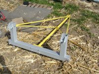
The beam is going to buckle where the brace from underneath meets the beam. This is where the opposing forces are all greatest. Putting the truss support directly above this point sandwiches that point so that the truss support above pushes down to help counter the force of the brace pushing up.

Exactly. If the upwards and downwards forces are on the lower support then there is less stress on the main beam. There are calculations available to figure the capacities with and without the supports but you would need to know how much force a given piece could take. Important thing to know is that it dramatically increases the capacity.
 
   / Built my boom pole today #22  
By doing this aren't you adding more total forces to this area therefore making it the weak point ?

Correct that you are adding more total forces. Incorrect that you are making it the weak point. The purpose is to create opposing forces that cancel each other.
 
   / Built my boom pole today #24  
Correct that you are adding more total forces. Incorrect that you are making it the weak point. The purpose is to create opposing forces that cancel each other.

How my thick head works is this. I am looking at the pole part let say 2x2x1/4" wall as being an undersized member for what he needs for the design. So he adds a truss to increase the stiffness and load carrying capacity to match that of a 2x4x1/4"wall pole. So regardless of which pole he uses the capacity would be the same and the failure point would be the same at the lower support leg.The only way to increase the load capacity would be to move the lower support leg to shorten the pole length not change the truss support leg location.
 
   / Built my boom pole today #25  
It is still interesting to see the boom mounted on the bucket...Plus educating. Good deal.
 
   / Built my boom pole today #26  
As long as you guys are doing structural analysis on boom poles, you might as well look at mine too. Here's about the only pic I have of it. Compared to others, it may seem upside down (but is setting upright in the pic below). Its all built on a dedicated subframe (no bucket required) which directly quick-hitches to my JD CX300 loader. The main tube is 2.5 inch OD, with about a 3/16" wall. The main struts are 1/8" wall three-quarter inch square tube. The jury struts are 1/2" square tube, welded to the clamp, the clamp is clamped around the main tube (not welded to it) at mid span. OK, I admit it, there is some aircraft building experience blended in here.

Its fully tested. My loader can lift about 2000 lbs. at the pins. Last year I was trying to lift a 36 foot steel k-bar truss (~500 lbs) off the tops of a couple of 6x6 poles set in the ground. Due to a forgotten fastener or two or four, the poles both broke before I lifted the truss off. It was 12 feet to the top of the truss from the ground. I was lifting in the middle, with a chain in a "V", spaced about ten feet apart to two points on the truss.
 

Attachments

  • P3210305.JPG
    P3210305.JPG
    692.4 KB · Views: 485
   / Built my boom pole today #27  
As long as you guys are doing structural analysis on boom poles, you might as well look at mine too. Here's about the only pic I have of it. Compared to others, it may seem upside down (but is setting upright in the pic below). Its all built on a dedicated subframe (no bucket required) which directly quick-hitches to my JD CX300 loader. The main tube is 2.5 inch OD, with about a 3/16" wall. The main struts are 1/8" wall three-quarter inch square tube. The jury struts are 1/2" square tube, welded to the clamp, the clamp is clamped around the main tube (not welded to it) at mid span. OK, I admit it, there is some aircraft building experience blended in here.

Its fully tested. My loader can lift about 2000 lbs. at the pins. Last year I was trying to lift a 36 foot steel k-bar truss (~500 lbs) off the tops of a couple of 6x6 poles set in the ground. Due to a forgotten fastener or two or four, the poles both broke before I lifted the truss off. It was 12 feet to the top of the truss from the ground. I was lifting in the middle, with a chain in a "V", spaced about ten feet apart to two points on the truss.

500 lbs at the end of that pole , looks like 6' or so ,is putting +/-3000lbs pounds of force on your connections and the load would be a load greater than your tractor lifting capacity ?
 
   / Built my boom pole today #28  
As long as you guys are doing structural analysis on boom poles, you might as well look at mine too. Here's about the only pic I have of it. Compared to others, it may seem upside down (but is setting upright in the pic below). Its all built on a dedicated subframe (no bucket required) which directly quick-hitches to my JD CX300 loader. The main tube is 2.5 inch OD, with about a 3/16" wall. The main struts are 1/8" wall three-quarter inch square tube. The jury struts are 1/2" square tube, welded to the clamp, the clamp is clamped around the main tube (not welded to it) at mid span. OK, I admit it, there is some aircraft building experience blended in here.

Its fully tested. My loader can lift about 2000 lbs. at the pins. Last year I was trying to lift a 36 foot steel k-bar truss (~500 lbs) off the tops of a couple of 6x6 poles set in the ground. Due to a forgotten fastener or two or four, the poles both broke before I lifted the truss off. It was 12 feet to the top of the truss from the ground. I was lifting in the middle, with a chain in a "V", spaced about ten feet apart to two points on the truss.


I like it. Good design, making better use of materials. The only suggestion I would make is to weld the struts to the center of the tube instead of clamp them.

a long structural member has 3 basic modes of stress. Tension(pulling), Compression(pushing) and shear(bending). Tension is the strongest mode, and you will get the most out of the material used. Compression is the next strongest, but considerably weaker than tension. Shear is the weakest mode. A good design always strives to place as much of the design load as possible in tension or compression. The above design illustrates this perfectly. The top angled struts are in tension, therfore are much stronger for their weight. The tensioned top struts place the main boom pole in compression. A column in compression will usually fail or buckle in the middle of it's span(compress a toothpic or matchstick between your fingers). The secondary struts lend support to the column at it's weakest point. Since the struts are offset to the side, this gives side to side support. Triangles are our friends.

You avoided shear alltogether... Well done sir...
 
   / Built my boom pole today #29  

Attachments

  • DSC102594.jpg
    DSC102594.jpg
    423.6 KB · Views: 302
   / Built my boom pole today #30  
How my thick head works is this. I am looking at the pole part let say 2x2x1/4" wall as being an undersized member for what he needs for the design. So he adds a truss to increase the stiffness and load carrying capacity to match that of a 2x4x1/4"wall pole. So regardless of which pole he uses the capacity would be the same and the failure point would be the same at the lower support leg.The only way to increase the load capacity would be to move the lower support leg to shorten the pole length not change the truss support leg location.

You are correct that no matter where the truss support is, the trussed beam is still stronger than the un-trussed beam. It's just going to be strongest if the support is directly over the leg. True that moving the leg out will create even more support than moving the truss support in, but that's due to other factors.

Take a look at the sketch that BCP posted (post #13). It's a good illustration of the principle. In that sketch the beam is able to bend without bending or breaking any other member of the structure. Imagine if the truss support were directly over the leg. The only way it could bend in that instance is for a weld to break or for some other member of the structure to stretch, bend or break.

In this particular instance the beam is plenty heavy for the application. We're splitting hairs a bit for the sake of discussion and for future reference.
 

Tractor & Equipment Auctions

2021 CATERPILLAR 259D3 SKID STEER (A51242)
2021 CATERPILLAR...
2008 Ford F-250 4x4 Ext. Cab Pickup Truck (A49461)
2008 Ford F-250...
2015 MACK GU713 WINCH TRUCK (INOPERABLE) (A50854)
2015 MACK GU713...
2008 CATERPILLAR 304C CR EXCAVATOR (A51242)
2008 CATERPILLAR...
2008 Kenworth T300 T/A Knuckleboom Crane Truck (A50323)
2008 Kenworth T300...
5K ANNULAR BLOWOUT PREVENTER (A50854)
5K ANNULAR BLOWOUT...
 
Top