You are using an out of date browser. It may not display this or other websites correctly.
You should upgrade or use an alternative browser.
You should upgrade or use an alternative browser.
Can I tee into PB and return for extra valve?
- Thread starter DiskDoctr
- Start date
- Views: 3440

More options
Who Replied?
/ Can I tee into PB and return for extra valve?
#11
WranglerX
Super Member
Would not a third function kit be answer to control grapple...
rScotty, this statement, and your drawing, kind of freaked me out. I am in the middle of adding a home-brew SCV for a grapple on my JD-4510 and my D03 subplate has no separate return to the tank. Plumbing goes from the loader's Power Beyond port to the "P" port on the SCV's subplate, then out of the "T" port to the next valve in the chain - in my case, there will be a 3 pt hitch log splitter - then back to the tank. Your drawing shows a separate return line for each valve. Mine has a single return for the whole series chain (I thought that was the whole point of plumbing valves in series). Am I plumbing this thing incorrectly? Do I need to try to find a D03 subplate with an additional return port?3. Each control valve stack will have it's own "return to tank" port and each return must be plumbed separately from each valve stack back to the Tank or Sump.
rScotty
Super Member
- Joined
- Apr 21, 2001
- Messages
- 9,679
- Location
- Rural mountains - Colorado
- Tractor
- Kubota M59, JD530, JD310SG. Restoring Yanmar YM165D
It's right until it gets to the SCV subplate. But I think you see what you need.rScotty, this statement, and your drawing, kind of freaked me out. I am in the middle of adding a home-brew SCV for a grapple on my JD-4510 and my D03 subplate has no separate return to the tank. Plumbing goes from the loader's Power Beyond port to the "P" port on the SCV's subplate, then out of the "T" port to the next valve in the chain - in my case, there will be a 3 pt hitch log splitter - then back to the tank. Your drawing shows a separate return line for each valve. Mine has a single return for the whole series chain (I thought that was the whole point of plumbing valves in series). Am I plumbing this thing incorrectly? Do I need to try to find a D03 subplate with an additional return port?
Instead of coming out the "T" port to the next valve you need to be coming out of the Power Beyond "PB" port to go to that next valve - which probably does mean a different control valve.
Every loader valve has to have its own path to the tank because it uses the "T" port to provide a path for the fluid exhausted from unpressurized side of the cylinders. That fluid has almost no pressure left, and needs an easy path back to the tank. Make it's hose a size larger than the pressure in hose.
Loader valves that have a Power Beyond "PB" port allow a path for pressurized flow to go straight through the valve and on to the next control. Be sure to get the specialized PB sleeve if you are going to use that port. If the PB port is not used, the sleeve is removed and a threaded plug blocks the port.
Bottom line is that PB ports (and the sleeve) are an extra cost option on most
valves. If you are a builder and tinkerer, always order your valve with the PB port and sleeve.
Did that answer the question?
luck,
rScotty
I'm sorry to say, you have raised more questions in my mind than you answered. You talk about "loader valves." I am using this subplate and this valve to run a grapple. I'm not sure I would call it a "loader valve." Are we talking about the same thing?Did that answer the question?
Attachments
rScotty
Super Member
- Joined
- Apr 21, 2001
- Messages
- 9,679
- Location
- Rural mountains - Colorado
- Tractor
- Kubota M59, JD530, JD310SG. Restoring Yanmar YM165D
OK. I'll get down to your subplate in a couple of paragraphs - where I call it a directional or diverter valve.I'm sorry to say, you have raised more questions in my mind than you answered. You talk about "loader valves." I am using this subplate and this valve to run a grapple. I'm not sure I would call it a "loader valve." Are we talking about the same thing?
But first, I originally used the term "loader valves" because of that nice Summit drawing and others which often show that way of adding circuits to loader control valves. is To avoid confusion, lets quit calling them loader valves and call them as they are: control valves. Loader valves are actually "two spool control valves". A similar valve for a grapple might be a "one spool control valve". Backhoes often have 6 or 7 spool control valves! Then we call it a "control valve stack" - although pedantically, even a single control valve is a stack of only one spool.
Apparently this daisy chain using multiple control valves is NOT what you are doing. But lets look at it anyway because it is common. Regardless of what the hydraulic flow is going to be used for, you can get there by simply daisy chaining together any number of control valves having any number of stacks from one to infinity as long as each valve stack has its own PB port and return to tank.
The advantage to a daisy chain is that every valve in the chain always has "live" power available to use.
The downside to a daisy chain of control valves is that you need multiple returns to the tank, multiple control valves are more expensive, and there are always losses, meaning the longer the daisy chain the less flow rate and pressure is available to the last valves in the series chain.
For these reasons, rear remotes are often short daisy chains with the chain ending at the the 3pt control. We end at the 3pt purely for mechanical convenience. The 3pt is in reality simply a single spool control valve that has a convenient (and often inaccessible) internal return to the tank cast into the rear housing.
The other way to add multiple circuits is to use a directional/diverter valve to make the basic hydraulic flow into an "either/or" type of "Y". What you are calling a "subplate" is what I call a "full flow directional valve" or diverter valve. Those will divert a flow into either one way or the other but not both.
The advantage is full power is available either way. The disadvantage is that only one way is active at a time.
Yes, there are partial flow directional diverter valves...and that may be what you have. If so it will be labeled as such on the valve body.... but lets look at the simpler either/or case for starters.
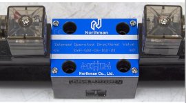
Control over which way is active is either by a manual lever or a push/pull solenoid like in your second photo. So when using a directional contol you will have flow to either circuit A or circuit B but not to both A+B at the same time.
If the directional control valve is getting its power from the loader control valve PB port, then circuit A could go to a grapple and circuit B could go back to a daisy chain of rear remotes and 3pt. That is not uncommon at all.
In that case, if the directional diverter valve is powering a single spool control valve to work the grapple, then the diverter valve itself does not require a return to the tank. The return to the tank is from the the the single spool control valve.
However, some directional diverter valves use a solenoid to only divert the flow - or a portion of the full flow - for an instant to fully open or close the grapple. In that case, the grapple doesn't have a manual single spool valve for fine control - it is either open or closed. But there still needs to be a path for the low pressure fluid expelled from the grapple cylinde to get back to the tank. Often that path will be on the directional control valve itself. It will be labeled as Tank or T. That flow does not have enough pressure to work anything else .
Everytime you work a two-way cylinder you have to have a return to the tank somewhere, and that fluid cannot be made to do more work.
Yes, theoretically the directional diverter could provide a choice between two daisy chains. Doing that all comes down to how much parasitic loss the circuits can live with before all the pressure is used up. If there are a lot of losses, designers will switch from the common open hydrauic system and go instead to a closed hydraulic system like JD's larger tractor use. In the closed hydraulic system there is a pressure reservoir to maintain ful pressure everywhere.
Compact and Utility size tractors do NOT use the closed system.We are OPEN hydraulic systems. Open means open to the atmosphere in the tank. Closed systems are not. They are complex and expensive and use different and special types of valves throughout.
Is this helping?
rScotty
rScotty, clearly you are the right guy to present this master class.
OK, if I understand your lesson correctly: when the grapple valve (sitting on the subplate) is closed, there is a continuous flow from the Power Beyond port on the loader valve, through the P port of the subplate, out of the T port of the subplate, to the log splitter valve and then back to the tank. No work is being done anywhere; there is just a continuous flow.
When the A solenoid on my grapple valve fires, it opens the A side of the grapple valve to the pressure on the subplate's P port, and sends that pressurized fluid to the A side of the grapple cylinders. At the same time, it opens the B side of the grapple valve to the unpressurized T port of the subplate to allow the B side of the grapple cylinder to empty back to the tank.
When the solenoid is uncharged again, the valve returns to neutral (closed) and the continuous flow resumes through the subplate (in the P port and out the T port), essentially bypassing the grapple valve entirely.
When the B solenoid on my grapple valve fires, it opens the B side of the grapple valve to the pressure on the subplate's P port, and sends that pressurized fluid to the B side of the grapple cylinders. At the same time, it opens the A side of the grapple valve to the unpressurized T port of the subplate to allow the A side of the grapple cylinder to empty back to the tank.
When the grapple valve is closed (in neutral), the flow is pressurized beyond the grapple valve and can be used to do work at the log splitter valve. However, the two valves cannot be used at the same time because the pressure will be taken by the first open valve and there will be little or no pressure left to do work at the second valve.
So, bottom line: in this setup, there is no need for a separate return line from the subplate of the grapple valve to the tank, as long as I don't plan to use the grapple valve and the log slitter valve at the same time.
Do I pass the test?
rScotty
Super Member
- Joined
- Apr 21, 2001
- Messages
- 9,679
- Location
- Rural mountains - Colorado
- Tractor
- Kubota M59, JD530, JD310SG. Restoring Yanmar YM165D
I think you have all the concepts right. So that part of the test is passed. And congrats for sticking to it.
The bad news is it implementing the knowledge. I'm still bothered by the fact that the subplate has a port labeled as a "T" port which you want to take to the log splitter. We were fine until the log splitter came along on the same circuit. I understand that you believe that the T port can sometimes be used as a pressurized flow & maybe it can. That looks like a specialized subplate made by some manufacturer for a special purpose and I don't know what it does. Why would a power port ever be labeled with a T?
Luckily we can figure it out. This is why there is a branch of hydraulics devoted to schematic diagrams for just this reason. A schematic of the subplate will show exactly what is going on inside the device.
So it's time for two things: One is a sketch of the system you plan to build. The other is a schematic diagram of the subplate and the solenoid valve. These schematics are common and are part of the technical spec for each part. Studying those will answer the question.
If you need a refresher on fluid schematics:
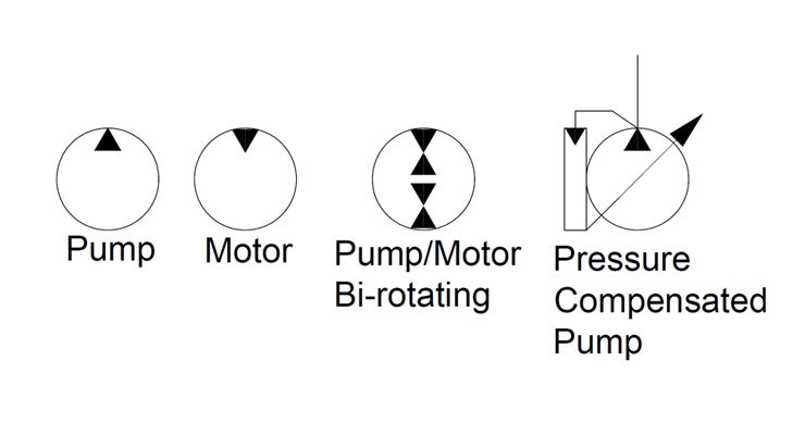
 www.fluidpowerworld.com
rScotty
The bad news is it implementing the knowledge. I'm still bothered by the fact that the subplate has a port labeled as a "T" port which you want to take to the log splitter. We were fine until the log splitter came along on the same circuit. I understand that you believe that the T port can sometimes be used as a pressurized flow & maybe it can. That looks like a specialized subplate made by some manufacturer for a special purpose and I don't know what it does. Why would a power port ever be labeled with a T?
Luckily we can figure it out. This is why there is a branch of hydraulics devoted to schematic diagrams for just this reason. A schematic of the subplate will show exactly what is going on inside the device.
So it's time for two things: One is a sketch of the system you plan to build. The other is a schematic diagram of the subplate and the solenoid valve. These schematics are common and are part of the technical spec for each part. Studying those will answer the question.
If you need a refresher on fluid schematics:
Hydraulic symbology 101: Understanding basic fluid power schematics - Fluid Power World
By Josh Cosford, Contributing Editor Out of any topic under the patio-sized umbrella of fluid power, hydraulic symbology garners the most requests from those wishing to learn more about fluid power. Reading any schematic with more than three symbols can be daunting if your experience is limited...
www.fluidpowerworld.com
rScotty
I don't find a flow drawing anywhere, but the subplate is at
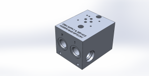
Attached are images of it from all sides.
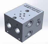
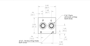
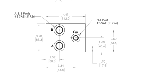
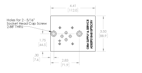
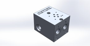
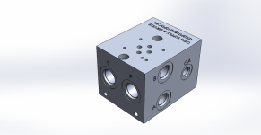
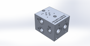
I chose this subplate specifically because it had the A & B ports on the same side, and it had the T & P ports that go through (so by using plugs in the non-used side, you can choose the valve's orientation). Most D03 subplates I found had A & B ports on opposite sides, and T & P ports on opposite sides (typically requiring 90-degree connections all around).
For my application, I wanted the A & B ports on the right side and the T & P ports on the same side, with the T port to the left of the P port. That way my hoses don't have to cross each other and I don't have to use any 90 degree connectors on the T or P lines.
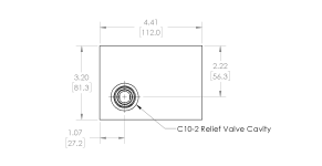
Other than the fact that it is "taller" than most D03 subplates I have seen, and the fact that it has a gauge port and a common cavity pressure relief valve port, both of which are plugged off, I was told it is a pretty standard D03 subplate, which will work on any D03 solenoid control valve. The valve I had fit perfectly onto it.
I don't know how to draw internal flows, but I have drawn the layout to the best of my ability. Sorry for the kindergarten drawing technique.
The tractor has a rear remote which comes off of the third spool of the 3-spool loader valve. The rear remote has two female 1/2-inch AG quick disconnects.
The tractor also has the Power Beyond kit installed. That kit currently has a line that comes off of the Power Beyond port of the loader valve, a male and a female 1/2-inch AG quick disconnect at the rear, and a line back to the tank. That is where the log splitter will eventually tie in.
I am cutting into the Power Beyond line and adding the D03 subplate and solenoid valve for the grapple.
Does this make sense?
Attached are images of it from all sides.
I chose this subplate specifically because it had the A & B ports on the same side, and it had the T & P ports that go through (so by using plugs in the non-used side, you can choose the valve's orientation). Most D03 subplates I found had A & B ports on opposite sides, and T & P ports on opposite sides (typically requiring 90-degree connections all around).
For my application, I wanted the A & B ports on the right side and the T & P ports on the same side, with the T port to the left of the P port. That way my hoses don't have to cross each other and I don't have to use any 90 degree connectors on the T or P lines.
Other than the fact that it is "taller" than most D03 subplates I have seen, and the fact that it has a gauge port and a common cavity pressure relief valve port, both of which are plugged off, I was told it is a pretty standard D03 subplate, which will work on any D03 solenoid control valve. The valve I had fit perfectly onto it.
I don't know how to draw internal flows, but I have drawn the layout to the best of my ability. Sorry for the kindergarten drawing technique.
The tractor has a rear remote which comes off of the third spool of the 3-spool loader valve. The rear remote has two female 1/2-inch AG quick disconnects.
The tractor also has the Power Beyond kit installed. That kit currently has a line that comes off of the Power Beyond port of the loader valve, a male and a female 1/2-inch AG quick disconnect at the rear, and a line back to the tank. That is where the log splitter will eventually tie in.
I am cutting into the Power Beyond line and adding the D03 subplate and solenoid valve for the grapple.
Does this make sense?
Attachments
-
 0000656_d03-aluminum-manifold-1-station-with-common-relief-cavity.png24.7 KB · Views: 100
 -
 0000655_d03-aluminum-manifold-1-station-with-common-relief-cavity.png28.8 KB · Views: 98
 -
 0000654_d03-aluminum-manifold-1-station-with-common-relief-cavity.png29.2 KB · Views: 100
 -
 0000653_d03-aluminum-manifold-1-station-with-common-relief-cavity.png28.2 KB · Views: 111
 -
 0000652_d03-aluminum-manifold-1-station-with-common-relief-cavity.png159 KB · Views: 92
 -
 0000651_d03-aluminum-manifold-1-station-with-common-relief-cavity.png157.8 KB · Views: 96
 -
 0000650_d03-aluminum-manifold-1-station-with-common-relief-cavity.png174.3 KB · Views: 94
 -
 0000649_d03-aluminum-manifold-1-station-with-common-relief-cavity.png173.5 KB · Views: 100
 -
![IMG_8905[1].JPG](/forums/data/attachments/711/711699-0aa485e464b11f34f067b6f6470a8bd0.jpg) IMG_8905[1].JPG1.3 MB · Views: 118
IMG_8905[1].JPG1.3 MB · Views: 118
rScotty
Super Member
- Joined
- Apr 21, 2001
- Messages
- 9,679
- Location
- Rural mountains - Colorado
- Tractor
- Kubota M59, JD530, JD310SG. Restoring Yanmar YM165D
I don't find a flow drawing anywhere, but the subplate is at
Attached are images of it from all sides.
I chose this subplate specifically because it had the A & B ports on the same side, and it had the T & P ports that go through (so by using plugs in the non-used side, you can choose the valve's orientation). Most D03 subplates I found had A & B ports on opposite sides, and T & P ports on opposite sides (typically requiring 90-degree connections all around).
For my application, I wanted the A & B ports on the right side and the T & P ports on the same side, with the T port to the left of the P port. That way my hoses don't have to cross each other and I don't have to use any 90 degree connectors on the T or P lines.
Other than the fact that it is "taller" than most D03 subplates I have seen, and the fact that it has a gauge port and a common cavity pressure relief valve port, both of which are plugged off, I was told it is a pretty standard D03 subplate, which will work on any D03 solenoid control valve. The valve I had fit perfectly onto it.
I don't know how to draw internal flows, but I have drawn the layout to the best of my ability. Sorry for the kindergarten drawing technique.
The tractor has a rear remote which comes off of the third spool of the 3-spool loader valve. The rear remote has two female 1/2-inch AG quick disconnects.
The tractor also has the Power Beyond kit installed. That kit currently has a line that comes off of the Power Beyond port of the loader valve, a male and a female 1/2-inch AG quick disconnect at the rear, and a line back to the tank. That is where the log splitter will eventually tie in.
I am cutting into the Power Beyond line and adding the D03 subplate and solenoid valve for the grapple.
Does this make sense?
I think your drawing is fine. Not knowing what is going on inside the DO3 is a bit of a problem. But the schematics are probably available. It may be that they are so simple that everyone but me already knows how they work.
A few questions.
1, What feeds flow to the rear remotes? Is there some sort of push/pull valve? Why does the drawing show two lines?
2. You label your loader control valve as 3 spools. Does it have three levers that move those three spools? Most loader controls have only two.
When you move the spool control lever off of center - say to lift the loader arms - several things happen. The tubular spool moves, and as it moves some some of the lands and grooves on the spool line up with various ports on the inside of the bore. One set of lands line up to block flow to the tank. A set of grooves line up to send the flow that was going to the tank to the extension side of the lift cylinde. At the same time, another set of lands was blocking the other side of the lift cylinder so that the arms would stay up in the air when the lever was centered. These lands that were not allowing oil to leave back side of the cylinder now are moved aside and grooves take their position to allow oil being expelled by the movement of the cylinder piston to go to the tank.
So a simple one-way movement of the lift spool lever actually does a number of things. It does so with very close tolerances which is why they cost so much to make. And that leads to my question 3...
3. What do you think is happening inside the DO3 when the solenoid is activated? Does it do all the things that the loader control spool valve does? Specifically, lets say that the "a" circuit is activated to extend the cylinder. As it extends, the piston moves and forces fluid out of the other side of the cylinder. But circuit "b" is closed. Does that expelled oil have a path out? Where?
rScotty