Conflict in my brain.

   / Conflict in my brain. #1  

RegL

Platinum Member
Joined
Aug 4, 2003
Messages
705
Location
Northwestern CT
Tractor
PT 1430
Several of us have been posting, for a couple of years now, about working the PT in hot weather and how when the oil gets hot it's less efficient and the tractor loses traction and power. And we have discussed better cooling methods and adding thermometers to the hydraulic tank.

Now I'm reading posts that the tram circuit is closed loop and the oil never gets back to the tank or through the cooler. If that's true it looks like we would need to add some kind of cooler just for the tram circuit. Maybe just fill the bottom of the tub up with ice cubes before we go mowing, lol.

Also , if the above is true, wouldn't the oil in the tank get overheated only by heavy pto use? To the contrary, I have made the tank to hot to touch by doing a lot of tramming. For instance, moving lots of brush long distances with the grapple bucket. What are some thoughts?
 
   / Conflict in my brain. #2  
RegL said:
Several of us have been posting, for a couple of years now, about working the PT in hot weather and how when the oil gets hot it's less efficient and the tractor loses traction and power. And we have discussed better cooling methods and adding thermometers to the hydraulic tank.

Now I'm reading posts that the tram circuit is closed loop and the oil never gets back to the tank or through the cooler. If that's true it looks like we would need to add some kind of cooler just for the tram circuit. Maybe just fill the bottom of the tub up with ice cubes before we go mowing, lol.

Also , if the above is true, wouldn't the oil in the tank get overheated only by heavy pto use? To the contrary, I have made the tank to hot to touch by doing a lot of tramming. For instance, moving lots of brush long distances with the grapple bucket. What are some thoughts?

I can certainly understand your difficulty in understanding the system. I'm having similar problems...

For example, why do you need a 4gpm charge pump to "prime and feed" a 16gpm hydrostatic pump? At least that's the picture I get from the previous posts here... Certainly makes me wish I had a GOOD schematic handy.

I can understand the need for a charge pump if the wheel motors have case drains -- since you "lose" oil out of those case drains that must be replenished in the circuit. But, how do you lose oil out of the circuit if there are no case drains on the wheel motors? What goes in the front wheel motor must come out the rear wheel motor. Does that mean that the systems without case drains in the wheel motors (such as my PT-425) are really open circuits, flowing back to the tank?
 
   / Conflict in my brain. #3  
Looking at my schematic, it looks like the excess from the charge pump feeds to the hydraulic cooler and back to the oil tank. Thats why you need 4 gallons of makeup. Basically 4 gallons per minute is fed through the cooler by the charge pump. I assume (the schematic does not show one) that there is some kind of restriction so that there is some pressure maintained in the charge pump discharge to feed the wheel motor pump, or perhaps the oil cooler and hoses are enought of a restriction.
 
   / Conflict in my brain.
  • Thread Starter
#4  
BobRip said:
Looking at my schematic, it looks like the excess from the charge pump feeds to the hydraulic cooler and back to the oil tank. Thats why you need 4 gallons of makeup. Basically 4 gallons per minute is fed through the cooler by the charge pump. I assume (the schematic does not show one) that there is some kind of restriction so that there is some pressure maintained in the charge pump discharge to feed the wheel motor pump, or perhaps the oil cooler and hoses are enought of a restriction.

Bob, my question is, do you see the oil in the wheel motor circuit being cooled at all?
 
   / Conflict in my brain. #5  
It is cooled because the charge pump is bringing several gallons a minute from the oil tank into the wheel motor circuit at the wheel motor pump inlet and then sending some of that backout through the cooler. When the oil is in the charge pump outlet some of it goes to the wheel motor circuit and some to the oil cooler. So basically there is a mixing of oil form the oil tank with that in the wheel motor circuit at the charge pump outlet. The wheel motor return also goes to the charge pump outlet which is the same section as the wheel motor pump inlet. I hope this is clearer.
 
   / Conflict in my brain. #6  
BobRip said:
Looking at my schematic, it looks like the excess from the charge pump feeds to the hydraulic cooler and back to the oil tank. Thats why you need 4 gallons of makeup. Basically 4 gallons per minute is fed through the cooler by the charge pump. I assume (the schematic does not show one) that there is some kind of restriction so that there is some pressure maintained in the charge pump discharge to feed the wheel motor pump, or perhaps the oil cooler and hoses are enought of a restriction.

Bob,

That pressure in the charge pump is around 325 psi. I believe that what ever oil is being pumped and not used by the wheel motors is dumped into the case drain, and then to the cooler. I have seen a number somewhere that equates to how many gal of fluid is pumped by the charge pump. It is based on the gpm of the main pump. It just be that some of that hot wheel motor fluid is bleed off into the case drain, in order for the charge pump to supply fresh filtered fluid, and not using recirculated fluid all the time. That would give us a logical answer why the hydraulic fluid get hot just by working the wheel motors.
 
   / Conflict in my brain. #7  
RegL said:
wouldn't the oil in the tank get overheated only by heavy pto use? To the contrary, I have made the tank to hot to touch by doing a lot of tramming. For instance, moving lots of brush long distances with the grapple bucket. What are some thoughts?
You can make the tank hot to the touch just by starting the engine and letting it run at full throttle for 10 minutes without moving the tractor. The reason the hydraulic fluid in the tank gets hot is because any time the engine is running, even if you are standing still and have no implements attached, both sections of the PTO pumps are still pushing fluid. The AUX PTO circuit, besides providing pressure for the quick attach, also provides the steering and lift pressure. The MAIN PTO circuit is always pumping, too. It is just bypassed back to the tank until the dashboard switch is flipped.

All HST systems do this. Fluid is always being pumped if the engine is running. It is just directed back to the tank if it isn't needed to perform any work. However, when the tractor is standing still, the HST is probably not the cause of the heat... the PTO pumps are.
 
   / Conflict in my brain. #8  
J_J said:
Bob,

That pressure in the charge pump is around 325 psi. I believe that what ever oil is being pumped and not used by the wheel motors is dumped into the case drain, and then to the cooler. I have seen a number somewhere that equates to how many gal of fluid is pumped by the charge pump. It is based on the gpm of the main pump. It just be that some of that hot wheel motor fluid is bleed off into the case drain, in order for the charge pump to supply fresh filtered fluid, and not using recirculated fluid all the time. That would give us a logical answer why the hydraulic fluid get hot just by working the wheel motors.

J_J, no doubt the case drains would recirculate oil back to the tank. However my machine does not have case drains. Looking at the attached schematic there is an outlet from the variable volume pump (#21) which goes to the hydraulic oil cooler (#13). The outlet of the cooler goes back to the tank. Mointed on oil cooler manifold (#7) is the temperature switch (not shown hear, but in the vehicle). Because of this I believe that the outlet of the recharge pump is fed to the oil cooler. I doubt that it is the high pressure side of the pump since then the oil cooler would have to run at very high pressure and the oil would flow through the cooler instead of the wheel motors. I don't think it is the recharge pump inlet since then you would be pulling unfiltered oil from the oil tank back through the oil cooler and bypass the filter. That leaves the recharge pump outlet. Of course since you have wheel motor case drains, then your schematics may be different. However the wheel motor case drains flow rate would be very variable, depending on the wear on the motors and would not be something that you could depend on. Again, I am not an expert in hydraulics, but this analysis seems logical to me. PT is taking advantage of the low pressure charge pump output to cool some of the hydraulic fluid. It seems very efficient to me.
 

Attachments

  • wheel motor hydraulic circuit 002.JPG
    wheel motor hydraulic circuit 002.JPG
    228.3 KB · Views: 199
   / Conflict in my brain. #9  
Bob,
As I suggested to Kent in the " Bleeding the closed loop system". Not to worry about his schematic being in Tennessee, it could be all wrong anyway.

I also have a 422 Bob, with the same schematic in the "Manual" as you are showing, there were many things had me puzzled with all of the schematics.
I gave one to JJ like the one you printed, I have apologized to him since then and all being well I will send you the schematic which is correct for my 422.
It's a tough job for a sr. sr. on his own but it was well worth the trouble.
As you will see there is no cooler shown, it is not connected into this circuit, also you will notice there is the addition of the treadle valve.
The Variable Volume Pump Part 2 is responsible for the operation of the wheel circuit, any excess oil is directed back into V V part one from where it is sent to a return port on the tank. Any excess in the circuit per se is exited to another return port on the tank from the treadle valve.
In a way it changes the whole perspective of what happens when. Very simple really we are using oil at our choice of pressure and letting any excess return to the tank.
Anyway so that you can all chew the fat some more, here is my wheel circuit on my 422 checked very carefully hose by hose. Have Fun.
 
Last edited:
   / Conflict in my brain. #10  
Bill, I suspect that PT has several versions of the hydraulics, but maybe only give out one version of the schematic. I traced my hydraulic cooler lines (but not the other lines) and it is as shown. Where is your cooler connected? I think that will help answer the question.
By the way my machine was built in year 2000 and the schematic was dated in 1998.

Edit - My PT422 has the hydroback and cable. I bet the other version has the valve at the treadle. Which is yours?
 
   / Conflict in my brain. #11  
NJBill said:
Bob,
As I suggested to Kent in the " Bleeding the closed loop system". Not to worry about his schematic being in Tennessee, it could be all wrong anyway.

I also have a 422 Bob, with the same schematic in the "Manual" as you are showing, there were many things had me puzzled with all of the schematics.
I gave one to JJ like the one you printed, I have apologized to him since then and all being well I will send you the schematic which is correct for my 422.
It's a tough job for a sr. sr. on his own but it was well worth the trouble.
As you will see there is no cooler shown, it is not connected into this circuit, also you will notice there is the addition of the treadle valve.
The Variable Volume Pump Part 2 is responsible for the operation of the wheel circuit, any excess oil is directed back into V V part one from where it is sent to a return port on the tank. Any excess in the circuit per se is exited to another return port on the tank from the treadle valve.
In a way it changes the whole perspective of what happens when. Very simple really we are using oil at our choice of pressure and letting any excess return to the tank.
Anyway so that you can all chew the fat some more, here is my wheel circuit on my 422 checked very carefully hose by hose. Have Fun.


Mr. Bill, Your wheel motor flow schematic for the 422 looks very close to the layout for my johnny home owner 180. ( the 180 has no oil cooler) so I am a little confused with your diagram showing the flow route on your wheel motors.:confused: 
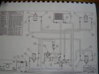
. How is your cooler plumbed in??? What's it hooked up to???> Your diagram is not showing the oil cooler.
 
   / Conflict in my brain. #12  
Hi Bob,
I bought my unit Mar 2004, The schematic was drawn Aug '98 and was revised May 2000.

As you can see I do have a treadle, I can only guess when they ran out of hydrovac parts, is when the treadle cxame into being.

The cooler line (1/4 inch) comes from the lower left port of the Sauer Danfuss valve, and leaves the cooler into the No 2 port on the tank.

We each have a PT, Now we have to wonder how many actual models are there ????
 
   / Conflict in my brain. #13  
NJBill said:
Hi Bob,

The cooler line (1/4 inch) comes from the lower left port of the Sauer Danfuss valve, and leaves the cooler into the No 2 port on the tank.

We each have a PT, Now we have to wonder how many actual models are there ????
What Sauer Danfass valve? The valves that control lift, curl and the Aux PTO?

My PT-425 (delivered in December 2000) sounds like Bob's PT-422...
 
   / Conflict in my brain. #15  
J_J said:
I thought this article would be of interest to anybody that has a hydraulic system.

Hydraulic Fluid Viscosity

JJ, you might have just found the "final answer"... :)

To quote that article:

Automatic transmission fluid, multi-grade engine oil and anti-wear, high VI (AWH) hydraulic fluid are commonly used in hydraulic systems that experience a wide operating temperature range. These fluids have a higher Viscosity Index (VI) than AW hydraulic fluids due to the addition of VI improvers. The higher the VI a fluid has, the smaller the variation in viscosity as temperature changes.
 
   / Conflict in my brain. #16  
I only have a rough drawing so far of the lift-tilt-aux pto valve circuit.
Kent
That's the Sauer-Danfass Valve
Rivco
You don't see the cooler in the wheel scematic, because on my PT it isn't.

For those of you who don't mind looking carefully at schematics, as I mentioned earlier the cooler line comes from the lift-tilt-aux pto valve bank, and from the cooler goes to No 2 return port of the tank.

Remember this is my PT, I'm positive there are many more variations of the hose layouts, even on the same designated models, mine is a PT 422.

Bill
 
Last edited:
   / Conflict in my brain. #17  
Forgive me for taking up your valuable time.
I've made a few changes on my lift tilt drawing, and a couple of photos to supplement my description of where does the cooler line come from.
Bill

The white tape in each photo is the cooler line leaving the Sauer Danfass, then sneaking into the tunnel to find it's way back to the engine cover.
Bill
 
Last edited:
   / Conflict in my brain. #18  
NJBill said:
Forgive me for taking up your valuable time.
I've made a few changes on my lift tilt drawing, and a couple of photos to supplement my description of where does the cooler line come from.
Bill

The white tape in each photo is the cooler line leaving the Suer Dana's, then sneaking into the tunnel to find it's way back to the engine cover.
Bill

Bill,

You are not taking up my valuable time, I am retired, and loving it. By all means continue to provide data on what ever machine that you have. We appreciate your efforts.

Your schematic of the joystick valve, shows a line running back to the oil cooler. Is there any other line that connects to this line and back to the cooler. One question is, is this the only line going back to the cooler. Next question, is there a line running from the tram pump back to the cooler? For instance, on my 1445, I have a coupling block on the right rear, that several lines connect. I believe Thai they are the case drains, and the output of the charge pump/tram pump. from this block, a line runs to the cooler

Does everyone know that you can bypass the temp switch that controls the fan. By doing this you get a jump start on the cooling , Just a SPST switch on the dash that you can toggle on whenever. You can then leave it in the auto mode, of manual mode. Some of the temp controls don't come on until around 150 degrees.
 
   / Conflict in my brain. #19  
This hydrostatic pump depicted below is similar to the one that I have in my 1445, but the charge pump is built in. I have a pump on the back , but it is the PTO pump. In the description they mention case drain, so therefore I am thinking that the charge pump overflow goes into the case drain and out to the cooling circuit. I am trying to get the guys at Eaton/Cessna to explain the pumps operation.

Surplus Center Item Detail
 
   / Conflict in my brain. #20  
JJ
I knew you would enjoy this situation. All my schematics show each hose on the PT, where they begin and end, so to answer your question that 1/4 inch hose takes care of all the cooling.
By the way one of the first changes I made on mine was to bypass the Temp switch at the cooler.
Heres a real handy man picture for you to enjoy, I've tried to show every port on each section, and what they do. As you can see there is only one port on what I call the VV part 1, and that goes to the tank, it appears to take the unwanted amount from the VV part 2 which is the wheel drive section.
The word tram is confusing me the only tram I know is like the one in the picture which I used to ride as a kid !!!
Bill

ps I'm also retired !!??
 
Last edited:

Tractor & Equipment Auctions

2019 Chevrolet Tahoe 4X4 SUV (A59231)
2019 Chevrolet...
40ft T/A Gooseneck Flatbed Equipment Trailer (A55851)
40ft T/A Gooseneck...
1977 Gleaner A630 Corn Head (A56436)
1977 Gleaner A630...
UNKNOWN  SKIDDED FRAC TANK (A58214)
UNKNOWN SKIDDED...
2009 Honda Odyssey Van (A55758)
2009 Honda Odyssey...
John Deere 652R 52in Stand-On Commercial Mower (A56857)
John Deere 652R...
 
Top