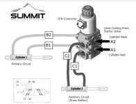
I am adding a thumb to my bucket, planning to use a diverter valve with solenoid and trigger on joystick to activate. The plan is to connect it so the curl and close are in the same postiton on the loader valve (left) so I can trigger it between curl and thumb closing to secure a load, and conversely triger between dump and open to drop a load. However the curl cylinder will need to retract and the thumb cylinder will need to extend to secure a load, and the opposite to drop the load. My plan would be to swap C1 and C2 in the diagram, so the curl cylinders work in the opposite direction of the thumb cylinder.
The valve supplier states that the upper and lower hoses on the valve must all be connected to the same end of each cylinder as shown in the attachment, or the valve will lock up. I could understand that if there are two cylinders on the same circuit with swapped hoses. However I cannot understand how it could make a difference to the valve which end of the cylinder is pressure and which one is return, when they are on separate circuits.
I am a relative hydraulics newbie, so I was hoping someone could explain how this works , or why it doesn't work.
Thank You.