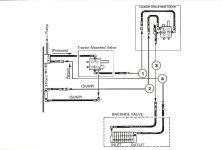
That diagram still leaves me with some questions. For instance, the "return" line that just sort of ends after the BH doesn't really define what it is. It doesn't show that it connects back to the sump.
Also, you will notice that the first two valves have three connections, power (P), power beyond (PB, they call it Bypass, but I like the Power Beyond name better, seems more meaningful), and tank (or sump) return (T).
These all make sense. But the backhoe (BH) valve only shows an inlet and outlet. That's fine, but they don't define or show in the valve schematic what the "outlet" is. Is it a PB (pressurized), or T (sump return)? Or maybe more likely, does the valve internally combine the two outputs into one low pressure return that should connect to the sump? You have to have someplace for fluid to go both when the valve is not active and when it is active, in the former case it will have the same pressure that is at the inlet, and in the latter case it had better not be connected to pressure or the work cylinder will not be able to get any work done.
If this schematic showed the outlet of the backhoe valve connecting up to the sump, it would make more sense to me. That return line can't just go nowhere or have a cap on it or the pump will kill itself pretty quickly.
By leaving the sump and the pump out of the diagram, and lines just floating in space, I am left with some unexplained questions. I also like the John Deere manual's hydraulic diagrams where they always show pressurized lines in red, and low pressure lines in blue.