Electric over hydraulic remote setup?

   / Electric over hydraulic remote setup? #21  
I'll take pictures of it all tommorow so you'll see what I have to work with. Im driving myself nuts thinking about what I want to do with it. I dont understand the 5th hose though. I thought the hydraulics were all in series and out of one would be the pressure into another valve. All the othe hydraulic lines are hard lines and its hard to distinguish what does what you know.
The problem is that if you have the 3 point set to go up while the grapple is closing, the grapple might not close until it is pushing out with enough force to lift the 3 point. See Hydraulic valve power beyond or high pressure carry over for some diagrams on how it works. If you look at your loader valve, it should have 7 ports (4 work ports and 3 other ports).

Aaron Z
 
   / Electric over hydraulic remote setup? #22  
Take some good pictures of the back above the 3pt so we can see where we might be able to install the other valves and or the QD ends if you go that way. Are you against making a mount off of the ROPS to place some manual valves and maybe a plate in back to mount the QD outlets? The EX3200 is a clean little tractor and we should be able to come up with a very nice setup for it. ;)
 
   / Electric over hydraulic remote setup?
  • Thread Starter
#23  
The problem is that if you have the 3 point set to go up while the grapple is closing, the grapple might not close until it is pushing out with enough force to lift the 3 point. See Hydraulic valve power beyond or high pressure carry over for some diagrams on how it works. If you look at your loader valve, it should have 7 ports (4 work ports and 3 other ports).

Aaron Z


I dont use both at the same time, grapple and 3pt. However if I try to lift the 3pt with the grapple installed it doesnt lift any real weight untill the grapple either opens or closes (depending on which way I have my hoses connected) OR if I hold the handle of the grapple in the center to allow pressure to the 3pt. Anytime I raise the 3pt the grapple lever will move and stays in position untill the 3pt hits the height my control lever wants it at. Pictures will be here today as soon as I get to the shop.
 
   / Electric over hydraulic remote setup?
  • Thread Starter
#24  
Take some good pictures of the back above the 3pt so we can see where we might be able to install the other valves and or the QD ends if you go that way. Are you against making a mount off of the ROPS to place some manual valves and maybe a plate in back to mount the QD outlets? The EX3200 is a clean little tractor and we should be able to come up with a very nice setup for it. ;)


Well, no but I got excited when I saw your picture thinking there may a more suitable way to save space and hydraulic hose. If anything a two spool valve would likely be just fine, I probably will never need the extra remote for anything. And to be honest the grapple remote will be open to use when the grapple bucket isnt on, so two would be just fine actually now that I really think about it.
 
   / Electric over hydraulic remote setup?
  • Thread Starter
#25  
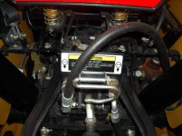
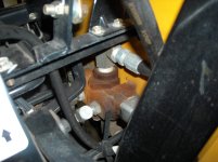
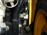
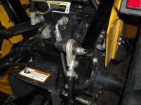
Ok, here are a few pics of the valve. Dont know if you can make it all out but from the "out" from the tractor goes to the valve, the opposing orifice on the valve loops back up the rear of the tractor and goes to "return". The other two lines just go to the front of the tractor as work outlets.

DSCN1244.jpgDSCN1245.jpgDSCN1246.jpgDSCN1247.jpg
 
   / Electric over hydraulic remote setup?
  • Thread Starter
#26  
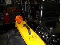
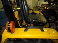
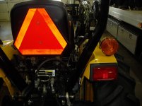
Here is some pics of the right fender area. The fender is decently stable, probably enough to mount a valve body to.

DSCN1248.jpgDSCN1249.jpgDSCN1250.jpg
 
   / Electric over hydraulic remote setup? #27  
The log splitter valve is probably not a good choice for the grapple, if it does not have a PB port and connected correctly.

The action of one valve should not affect the log splitter valve if the log splitter valve is connected correctly.

If your log splitter valve only has 4 hoses, then it is not a PB type valve, and you run the risk of damage.

You should probably remove the log splitter valve and install a three spool valve for the remotes., and use one of the spools for the grapple, or add a diverter valve to the front curl circuit, and us the joystick curl circuit for the grapple. .
 
   / Electric over hydraulic remote setup?
  • Thread Starter
#28  
I guess im trying to wrap my head around the 5th hose thats suppose to be coming out of the valve, I understand its to go back to the tank but thats about it. I've tried reading a few things about the subject buts its just not clicking in my head. Cub makes a rear remote kit for this tractor, part kit number RR300.

Here is the parts breakdown:
Parts and Diagrams for Cub Cadet RR300 Rear Remote


It doesnt look all that extensive really. I wish I could get an instruction sheet PDF to see how and where to install this "5th line" to go back to the tank. Everything is so jambed packed under the tractor I dont really know what i'm looking at.
 
   / Electric over hydraulic remote setup? #29  
That link does not work for me.

On most single spool valve, you would have an

IN port -from pump
OUT port- cyl expended fluid to tank
work port A - to cyl
Work port B - to cyl
Maybe a PB port - to down stream valve

All return lines should go to tank.

Return hoses can be teed together.

Can also run it into the fill cap.
 
   / Electric over hydraulic remote setup? #30  
I guess im trying to wrap my head around the 5th hose thats suppose to be coming out of the valve, I understand its to go back to the tank but thats about it. I've tried reading a few things about the subject buts its just not clicking in my head. Cub makes a rear remote kit for this tractor, part kit number RR300.

Here is the parts breakdown:
Parts and Diagrams for Cub Cadet RR300 Rear Remote


It doesnt look all that extensive really. I wish I could get an instruction sheet PDF to see how and where to install this "5th line" to go back to the tank. Everything is so jambed packed under the tractor I dont really know what i'm looking at.

I might be wrong, but looking at how the line runs, I don't think that you need a valve with power beyond. I think that you can just run the pressure line from the left side of your loop to the pressure port on a valve and then have the tank line off of the valve go back to the right side of the loop. I'm thinking that the side marked return just dumps into the tank and does not go any place else. If this is the case, then you do not need the 3rd power beyond line that has been talked about.
 
 
Top