electrical relays

   / electrical relays #21  
Then you could open a radio shack, oh wait, that's been done :)
 
   / electrical relays #22  
Just because it is cold and snowing outside, and I don't have much to do, I thought I would go on an informative tirade one more time to help describe the "why" of relays. There still seems to be some lingering lack of understanding why these things are so darn useful. This is going to be a "book" so if you don't like to read, now would be a good time to skip on to the next topic.

One of the things I like to do to illustrate my point is to "go big" on explanations. So I am going to use a "big" example of relay control.

Lets say you are the lock keeper down at the panama canal. You are sitting up in a control tower some distance from the actual lock that you are going to open and close. Now these locks weigh weigh many tons and are driven by motors of thousands of horsepower that power gear systems that actually swing the gates of the lock themselves. What I am trying to describe here is huge motors, huge gear trains, huge doors. These motors require huge voltages and currents to operate.

But in front of the lock keeper is a console with a a little switch on it that says open and closed. From that tiny switch is a few hundred yards of small wire that goes out to the control room where all of those huge motors are located.

The question is how is this tiny switch and those tiny wires going to control those huge motors located so far away?

Of course some of you don't even see a problem at all. Your bliss derives from a lack of knowledge of Ohms law. Byt others are starting to have some doubts about that tiny switch and those long tiny wires being able to control such a huge load. And as well you should.

Enter the concept of the relay. A device that can be actuated by a small voltage and small current and can control large voltages and large currents. Or in this case we are probably talking about relay's controlling even larger relays and likely many of them.

So you see the guy up in the controller is just controlling a much larger chain of events when he flicks his little switch to say "open". And it would not matter if he was hundreds of miles or even thousands of miles away. He could still control the huge chain of events to make those huge doors swing open. Such is the magic of the relay. A device that spans distance and a huge amount of power.

I hope this absurd little dissertation broaden the outlook of some and made you think a little. And the world would be a different place if someone didn't come up with the idea of a relay. :)
 
   / electrical relays #23  
Next on to resonance and IC timers :)
K0UA - your description is great and I might use it with my son, better than the dry talk about current or voltage amplification.
I wonder how many people know that relays were used as switching devices for phones and computers and how they eventually got replaced by tubes, and then transistors.
 
   / electrical relays #25  
Just because it is cold and snowing outside, and I don't have much to do, I thought I would go on an informative tirade one more time to help describe the "why" of relays. There still seems to be some lingering lack of understanding why these things are so darn useful. This is going to be a "book" so if you don't like to read, now would be a good time to skip on to the next topic.

One of the things I like to do to illustrate my point is to "go big" on explanations. So I am going to use a "big" example of relay control.

Lets say you are the lock keeper down at the panama canal. You are sitting up in a control tower some distance from the actual lock that you are going to open and close. Now these locks weigh weigh many tons and are driven by motors of thousands of horsepower that power gear systems that actually swing the gates of the lock themselves. What I am trying to describe here is huge motors, huge gear trains, huge doors. These motors require huge voltages and currents to operate.

But in front of the lock keeper is a console with a a little switch on it that says open and closed. From that tiny switch is a few hundred yards of small wire that goes out to the control room where all of those huge motors are located.

The question is how is this tiny switch and those tiny wires going to control those huge motors located so far away?

Of course some of you don't even see a problem at all. Your bliss derives from a lack of knowledge of Ohms law. Byt others are starting to have some doubts about that tiny switch and those long tiny wires being able to control such a huge load. And as well you should.

Enter the concept of the relay. A device that can be actuated by a small voltage and small current and can control large voltages and large currents. Or in this case we are probably talking about relay's controlling even larger relays and likely many of them.

So you see the guy up in the controller is just controlling a much larger chain of events when he flicks his little switch to say "open". And it would not matter if he was hundreds of miles or even thousands of miles away. He could still control the huge chain of events to make those huge doors swing open. Such is the magic of the relay. A device that spans distance and a huge amount of power.

I hope this absurd little dissertation broaden the outlook of some and made you think a little. And the world would be a different place if someone didn't come up with the idea of a relay. :)
The older among us may remember when our headlight dimmer switch was on the floorboard, left of the clutch pedal. It made a real loud "thunk" when you pressed it with your foot. Nowadays the headlight dimmer is on a little tiny stem on the steering column and it is a tiny "click". The old high current foot switch has been replaced with the tiny switch on the steering column and a relay.

Not as exciting as the canal example that James used above, but you don't have to worry about getting a cargo ship stuck sideways in it. 😂
 
   / electrical relays #26  
relay testers are common in automotive. surprised people haven't seen them

 
   / electrical relays #27  
Alligator clips are a lot cheaper and pinouts are never a secret. A relay doesn't cost much more with a socket and pigtail. (u only need one) Wouldn't take much then for a guy to test with a $6 VOM from HFT and jumper from a battery to energize.

I bet somewhere there's a light bulb tester, too. :sneaky:
 
   / electrical relays #28  
Alligator clips are a lot cheaper and pinouts are never a secret. A relay doesn't cost much more with a socket and pigtail. (u only need one) Wouldn't take much then for a guy to test with a $6 VOM from HFT and jumper from a battery to energize.

I bet somewhere there's a light bulb tester, too. :sneaky:
Testers like i linked save time for people who do it for a living.. you can also use a light bulb in place a of a multimeter, I will still own a multimeter...
 
   / electrical relays #29  
This seems silly to me. You close the switch to energize the coil and closes the contact which then supplies voltage to the load. Why not just have the switch in place the the relay contact? Hmmmmm, I'm sure there must be a reason but it escapes me at this time.
Because you can bank them up without overloading the switch as the only current the switch provides is picking up the coil.
 
   / electrical relays
  • Thread Starter
#31  
James, Thanks for the definitive explanation. I don't think I'll go that far; my luck I'd sink the ship!

Dale, Once again you come through with an easy to follow diagram to simplify a question. Thanks once more. Once I figure out how to bookmark anything I'll do so for future references.

LD1, You are correct, a Flasher Unit is cheap and will be much simpler to just replace than spend $ on parts and pieces to construct something that I may never again need to use. Thanks for the insight and thought.

LittleBill21, Thank you for assisting me in showing people that a relay tester is indeed in the marketplace and sold. I probably just had the wrong component plugged into it and that's why it was sparking. So I butchered up a piece of test equipment needlessly.

Oh well, I can always get another. I bought it just for the purpose of testing the glow plug relay if I ever needed to do so. I haven't needed it for that yet and hopefully won't. Although I now see that it's maybe not even a relay but rather a glow plug "Timer". It appears that proper wording is critical with these components. In my defense and lifetime though, I have heard the flasher called a relay before.

My thanks to all who've chimed in to help this electrical dufus get his vocabulary straight. I am quite embarrassed to having admit I'm a dufus in this respect thus I'd really rather put this issue to bed now that I'm better educated on wording. Don't worry, I'll probably have another dumb question for you all to chuckle over whilst educating me again in the future. I do now know something about electrical that I didn't before. Greg
 
   / electrical relays #32  
3 pin are generally rare. there is usually a post that is meant to be mounted to ground, this removes the 1 pin needed for coil. there would be generally be hot side coil and then the load, and the battery terminal. sending 12v to the hot side coil, generally activates the coil
 
   / electrical relays #33  
cheapest ... quick and easy...way to check a relay is to swap it for another that's the same.

most vehicles or equipment that have relays have more than 1.
 
   / electrical relays #34  
One instance I had where a multimeter caused me a wrong diagnosis:

The airconditioner on the (previous) tractor stopped putting out cold air. OK then, check that the electrically operated clutch on the compressor was getting 12v. Yep, multimeter registered 12v when ac knob rotated to the ON position. (Engine not running at this time)

So - problem must lie elsewhere, I reasoned.

Turns out that the 12v it was getting was UNDER NO LOAD, but when the engine was running and you asked the clutch to engage, the 12v source could not supply enough current, due to a dodgy connection somewhere upstream.

This was confirmed when I got a "tester pen", which utilised a filament tube (light) which drew some real current when applied to the test point. it didn't light up, even though the multimeter indicated 12v.

So I tracked back through the wiring, found the dodgy connection, and everything was cool again!
 
   / electrical relays #35  
Now there are relays..... This was very popular in early telco crossbar switches . Until most everything went solid state.... Spent many a hour with close association with these. In comparison the average relay found in car/truck/tractor applications are very simple....
 

Attachments

  • AK1_wire_spring_relay.jpeg.jpeg
    AK1_wire_spring_relay.jpeg.jpeg
    64.2 KB · Views: 123
  • main-qimg-444ef7bdf60e9fd3f9003f13c57695c9-pjlq.jpg
    main-qimg-444ef7bdf60e9fd3f9003f13c57695c9-pjlq.jpg
    53.7 KB · Views: 126
   / electrical relays #36  
3 pin are generally rare. there is usually a post that is meant to be mounted to ground, this removes the 1 pin needed for coil. there would be generally be hot side coil and then the load, and the battery terminal. sending 12v to the hot side coil, generally activates the coil
A three pin can be a possibility, though I haven't personally seen one

But modern stuff switches the ground.

Meaning that the 12v supply feeding the coil and the 12v supply feeding the high current load "can" be one and the same.

Single 12v supply, capable of handling the current of both the load and coil.

Then the output to the load, and the coil ground side going to the switch.

Not very many "hot" wires on cars anymore with switching the grounds.
 
   / electrical relays #37  
One instance I had where a multimeter caused me a wrong diagnosis:

The airconditioner on the (previous) tractor stopped putting out cold air. OK then, check that the electrically operated clutch on the compressor was getting 12v. Yep, multimeter registered 12v when ac knob rotated to the ON position. (Engine not running at this time)

So - problem must lie elsewhere, I reasoned.

Turns out that the 12v it was getting was UNDER NO LOAD, but when the engine was running and you asked the clutch to engage, the 12v source could not supply enough current, due to a dodgy connection somewhere upstream.

This was confirmed when I got a "tester pen", which utilised a filament tube (light) which drew some real current when applied to the test point. it didn't light up, even though the multimeter indicated 12v.

So I tracked back through the wiring, found the dodgy connection, and everything was cool again!
in this case a voltage drop test would have confirmed it, with a volt meter.
 
   / electrical relays #38  
Now there are relays..... This was very popular in early telco crossbar switches . Until most everything went solid state.... Spent many a hour with close association with these. In comparison the average relay found in car/truck/tractor applications are very simple....
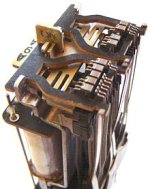
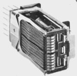
Spent some time cleaning those nasty things in the early part of my career. Before everything was solid state. Didn't like it much. We only had two of those PBX's left. Both were NEC (Nippon Electric Corp.) One was the small NA120 and the other was the NA409
 
   / electrical relays #39  
I don’t understand the comments about 3 pin relays being rare. They’re quite common. They’re all over the place. Just Google it. Flasher relays, horn relays, etc. Used all over the place in automotive, industrial, electronics, appliances, etc. In the general case, a three pin relay is just a Single Pole Single Throw (SPST) relay in which the load and coil share a common pin (See picture below). I’ve seen & used both NO and NC varieties. The advantages of a three pin relay are lower relay cost and you only have one common/ground connection out of the relay. Three pin relays are used less often than 4 and 5 pin relays so you don’t see them much in aftermarket because manufactures churn out 4 and 5 pin at such low cost. But for an OE buying large quantities, when a 3 pin can be used, it lowers manufacturing cost.

As for a relay tester, I suppose you could have one for the standard automotive relay form factors (Standard ISO, mini ISO & Micro ISO terminal footprints), but there’s an almost infinite variety of relay footprints out there and I don’t think a universal relay tester would be practical. Even in the ISO relay footprints, there are thousands of non-standard internal wiring configurations that would be cost prohibitive to build a tester to test them all.


1641573188586.png


picture from this article on relays…Relay article
 
   / electrical relays #40  
Many so called 3 pin also use the case and mounting bolts for ground.
 

Tractor & Equipment Auctions

(INOPERABLE) GEHL 8K TELEHANDLER (A58214)
(INOPERABLE) GEHL...
MASSAGE CHAIR (A58214)
20800 (A56859)
20800 (A56859)
IRET13 ELECTRIC TRICYCLE (A58214)
IRET13 ELECTRIC...
UNUSED RAYTREE RMPP680 HYD POST POUNDER (A60432)
UNUSED RAYTREE...
204549 (A52707)
204549 (A52707)
 
Top