AndyR
Gold Member
Mark,
I finally got my hands on the schematic for the L3710 and will post that seperately when I match the scans together. Before I go any further I have to admit that Kubota has some pretty strange ways of documenting things[image]/w3tcompact/icons/eyes.gif[/image] As I am in the process of wiring up lights on the new canopy I also discovered how wimpy the factory wiring is /w3tcompact/icons/shocked.gif /w3tcompact/icons/mad.gif /w3tcompact/icons/shocked.gif. I even found a point where the main POSITIVE battery cable presses hard against the radiator frame (which my dealer confirmed had been the point of at least one fire that they know of). Not good news![image]/w3tcompact/icons/sad.gif[/image] Again, I will post pictures and suggestions once I am done with the project.
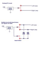
Now as to your flashers. Looking at the Kubota diagrams they do indeed switch the ground legs though a diode blocking arrangement so the you have right on, left on, or both on (hazard). Kubota uses three relays and a "hazard unit" [mystery device with 3 leads that looks like it could be an electronic flasher module as it is common with pin 3 of all 3 relays, pin 3 looks like the NO contact], one each for right and left and one for the flashers (at least according to the schematic - I have not needed to pull the instrument cowling off just yet to verify this).
Now, when I started writing this message I thought I had everything all worked out - but the more I checked your old messages the more confused I became!/w3tcompact/icons/crazy.gif How many relays do you have now (in the tractor - not in your possession). If I understood everything you have two electronic relays that are on-demand flasher modules with single outputs. Any conventional relays? any schematic of your current wiring?

