nickel plate
Veteran Member
Continued from part 1: 4/22/2011
I already had one set of rear remotes for the log splitter but late last year I installed a TnT for the box scraper which meant that I had to add a second set of rear hydraulic remotes. I knew a grapple install was not too far off so when that time came about it made sense to take advantage of tilt cylinder remotes to power the MIE grapple.
Now to figure out the hydraulic hose routing from the back of the NH TC40 to the grapple's single hydraulic cylinder. The right side of the tractor was already factory overloaded with pipes and hoses for the FEL so I chose the wide open left side for the new grapple run.
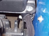
Photo 2 shows the two 3/8" hoses making their first lazy 90 degree turn running through a hawse pipe (my U. S. Navy days) a few feet from the remotes. I made it out of black ABS pipe, a smaller diameter glued inside a larger and top bolted through a convieniant factory drilled hole along side the seat in the bottom frame support of the fuel tank then wrapped that set of hoses that continue under the tractor in a black nylon protection sleeve.
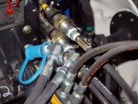
Photo 3 shows the first set of 1/2" QDs through a bracket at the loader arm upright. QDs are necessary here in order to remove the FEL from the tractor due to the hoses attachment running along the left loader arm. I shaped this custom bracket out of 4"x4"x1/4" angle stock and through bolted it into the lower end of the loader arm upright (the docking point for the FEL) using grade 8 bolts and stop nuts. With the clutch depressed I still have 2-1/2" of clearence.
The next set of hoses on the other side of the bracket leading up to the left loader arm are positioned in an "S" shape providing enough slack, similar to hoses on the right side that raise and lower the FEL and are also wrapped in a black nylon protection sleeve.
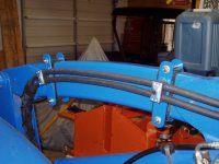
The last two photos show the routing of the hoses along the FEL arms. Being a non-welder and not wanting to make a huge mistake in placement of the two double hose clamps, I had a friend weld them onto a piece of 1-1/2"x7-1/4"x1/4" flat stock and along with a set of doublers on the other side, I placed them on a full wrapped piece of thick bedliner rubber and compressed with 5/16" grade 8 bolts and stop nuts.
Continued.
I already had one set of rear remotes for the log splitter but late last year I installed a TnT for the box scraper which meant that I had to add a second set of rear hydraulic remotes. I knew a grapple install was not too far off so when that time came about it made sense to take advantage of tilt cylinder remotes to power the MIE grapple.
Now to figure out the hydraulic hose routing from the back of the NH TC40 to the grapple's single hydraulic cylinder. The right side of the tractor was already factory overloaded with pipes and hoses for the FEL so I chose the wide open left side for the new grapple run.
Photo 2 shows the two 3/8" hoses making their first lazy 90 degree turn running through a hawse pipe (my U. S. Navy days) a few feet from the remotes. I made it out of black ABS pipe, a smaller diameter glued inside a larger and top bolted through a convieniant factory drilled hole along side the seat in the bottom frame support of the fuel tank then wrapped that set of hoses that continue under the tractor in a black nylon protection sleeve.
Photo 3 shows the first set of 1/2" QDs through a bracket at the loader arm upright. QDs are necessary here in order to remove the FEL from the tractor due to the hoses attachment running along the left loader arm. I shaped this custom bracket out of 4"x4"x1/4" angle stock and through bolted it into the lower end of the loader arm upright (the docking point for the FEL) using grade 8 bolts and stop nuts. With the clutch depressed I still have 2-1/2" of clearence.
The next set of hoses on the other side of the bracket leading up to the left loader arm are positioned in an "S" shape providing enough slack, similar to hoses on the right side that raise and lower the FEL and are also wrapped in a black nylon protection sleeve.
The last two photos show the routing of the hoses along the FEL arms. Being a non-welder and not wanting to make a huge mistake in placement of the two double hose clamps, I had a friend weld them onto a piece of 1-1/2"x7-1/4"x1/4" flat stock and along with a set of doublers on the other side, I placed them on a full wrapped piece of thick bedliner rubber and compressed with 5/16" grade 8 bolts and stop nuts.
Continued.
Attachments


Last edited: