Ford 4140 Power steering control valve - which holes do plungers go?

   / Ford 4140 Power steering control valve - which holes do plungers go? #1  

CurtisGrover

New member
Joined
Aug 1, 2022
Messages
4
Tractor
1963 ford 4140 HD Industrial Tractor Backhoe Loader
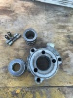
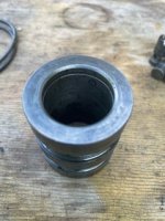
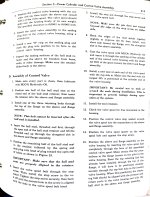
My tractor is a 1963 ford 4140 HD Industrial 4-cylinder gas with drag link assist power steering. I just purchased the tractor and have gone through everything that needed repair except no power steering. I have a new pump 1350 psi and have fixed all the leaks in the lines. The PO rebuilt the power steering cylinder and removed the control valve. The control valve C0NN3A730B has 3 plunger ports only, not 4 as in photo of a control valve that I have seen. I suspect that the PO of the PO may have assembled the plungers wrong. Do you know the correct assembly of the 3 plunger control valve (4 plungers, 2 springs, 2 horned plungers, 2 balls)? Also, which way does the center valve install? There is a groove on the inside at the bottom (or top depending on orientation). I hope you can help because there is very little info on this. Thank you
 

Attachments

  • image0-25.jpeg
    image0-25.jpeg
    79.3 KB · Views: 69
  • image1-10.jpeg
    image1-10.jpeg
    65.7 KB · Views: 80
   / Ford 4140 Power steering control valve - which holes do plungers go? #2  
Don't know if this helps as it isn't much clearer, but here you go
 

Attachments

  • Power Assist Steering Cylinder_1.jpg
    Power Assist Steering Cylinder_1.jpg
    912.4 KB · Views: 82
  • Power Assist Steering Cylinder_2.jpg
    Power Assist Steering Cylinder_2.jpg
    1.5 MB · Views: 88
  • Power Assist Steering Cylinder_3.jpg
    Power Assist Steering Cylinder_3.jpg
    1.5 MB · Views: 75
   / Ford 4140 Power steering control valve - which holes do plungers go?
  • Thread Starter
#3  
Thank you for the reply but my tractor is the heavy duty industrial with drag link power assist. I have tried the special plungers in every hole but still it made no difference. I have the FO20 manual and after reading it over again I'm going to start at the beginning and follow the procedure to disconnect the cylinder at the shaft and rotate the steering from left to right 6 times (or more) to bleed out the air. I have installed a 3000 psi pressure gauge in series between the pump output and control valve pressure port input but have yet to get a pressure reading when turning the wheel against the hard stop in either direction. It's supposed to be 1350 psi for the pump. I took a deadhead pressure measurement and only got 500 psi repeatable reading. I have fixed several line leaks in the steel hose sections of the PS hydraulic lines but I may have a minor leak between the reservoir and the PS pump so I will fix that tomorrow and update the thread in case it helps anyone else with their 1963 Ford 4140 HD Industrial tractor backhoe loader.

I have already completely power washed away all the years of grime and oil buildup around the whole tractor and removed the cast iron nose. Replaced the radiator with the non-cooler version and installed a heavy duty transmission cooler for the power steering because the original radiator with the cooler cannot be found anywhere for any price. The radiator it had couldn't be repaired and the shop said they could make one for $900. I bought the all purpose series 4000 tractor radiator for $250 delivered and $45 for the transmission cooler (actually $30 with Napa rewards and AAA discount). I mounted it in front of the radiator. The water pump leaked around the shaft so I replaced that and found no gasket on the thermostat housing so I got one. The carburetor leaked and I installed a new gasket. I replaced a few dried out orings in the hydraulics but nothing major. All the lift and pivot bushings are in excellent condition and well greased, no welds or cracks anywhere on the tractor, backhoe, or loader. The engine oil pressure is 50 psi. I will change the oil/filter very soon as it is black. I have painted the frame and engine ford blue and am painting the rest school bus yellow. This tractor is a beast and indestructible. Now if I can just get the power steering sorted out I will be very happy.
 
   / Ford 4140 Power steering control valve - which holes do plungers go? #4  
This is a drag link power assist from the Ford service manual, but it also shows a power assist cylinder in the nose for HD tractors. My impression was that yours is on the left side.
500 psi definitely won't get it.
Hard to assist otherwise without the detail.
 
   / Ford 4140 Power steering control valve - which holes do plungers go?
  • Thread Starter
#5  
This is a drag link power assist from the Ford service manual, but it also shows a power assist cylinder in the nose for HD tractors. My impression was that yours is on the left side.
500 psi definitely won't get it.
Hard to assist otherwise without the detail.
The cylinder is on the right side rear of front axle.


   / Ford 4140 Power steering control valve - which holes do plungers go? #6  
Got it. It is not an assist cylinder combo, but rather a gearbox assist. Here are the pertinent pieces out of the Ford SM
 

Attachments

  • HD_Steering_Control_Valve_1[1].jpg
    HD_Steering_Control_Valve_1[1].jpg
    1 MB · Views: 81
  • 2 HD Steering Control Valve.jpg
    2 HD Steering Control Valve.jpg
    1.2 MB · Views: 73
  • 3 HD Steering Control Valve.jpg
    3 HD Steering Control Valve.jpg
    919.4 KB · Views: 69
  • 4 HD Steering Control Valve.jpg
    4 HD Steering Control Valve.jpg
    907.6 KB · Views: 76
  • 5 HD Steering Control Valve.jpg
    5 HD Steering Control Valve.jpg
    1.5 MB · Views: 80
   / Ford 4140 Power steering control valve - which holes do plungers go?
  • Thread Starter
#7  
I don't have a 4 bore control valve, mine is a 3 bore control valve as seen in the attached photos in my original post. The intent is to determine which plungers go into which bore hole and which way does the center valve install (groove down or up) because I have no idea if the PO or the PO of the PO messed with it. I know how it disassembled, I took photos. I want to eliminate the possibility of the control valve being a problem but I have tried moving the horned plungers around anyway with no effect. Also the FO20 manual paragraph 64 says that the pump return port anti-cavitation valve is not used on the heavy duty industrial tractor control valve and there was not one in my control valve return port. The manual does not show the 3 bore control valve and only states to reinstall the components in the order they were removed. This control valve has a pressure port, return port, and 2 ports going to the cylinder. I have verified all lines are connected properly. I'm an engineer for 40 years and can't stop until I solve a problem... it may be that the new pump is bad or it could be something else but I still want to know the correct installation of the plungers and center valve for the 3 bore control valve. I do appreciate your help... thank you
 
 
Top