Grading GC1720 - Deadheading hydrostat?

   / GC1720 - Deadheading hydrostat? #21  
I believe on MF GC 17XX (05 to 20) series with ISEKI 3 cylinder diesel, all implements are are run off the pump in HST....

Dale

I seriously doubt that. How would that even be possible?. As with the swash plate in neutral the hydrostat pump make zero flow, there for zero pressure would be developed. Besides the first part of the paper he posted said the charge pump function was run off of the implement pump up on the engine... So NO>
 
   / GC1720 - Deadheading hydrostat? #22  
I seriously doubt that. How would that even be possible?. As with the swash plate in neutral the hydrostat pump make zero flow, there for zero pressure would be developed. Besides the first part of the paper he posted said the charge pump function was run off of the implement pump up on the engine... So NO>

Begging your pardon BUT there is no pump off camshaft of engine on the MS GC 17XX (05-20) series ... All pumps are located in HST housing all hydraulic plumbing originates on HST housing...... If I had not lost the copy of service manual in computer crash it would be easy to prove it....

THE flywheel end of engine block is solid ( and space directly next is occupied by muffler), and the timing gears for cam shaft and belts and pulleys for water pump and alternator occupies the "front" in close to radiator for engine (which is mounted reversed) ... Only thing I can find that may run off camshaft is diesel fuel pump....

Only "connection" from engine to all working parts of tractor is drive shaft off water pump, alternator belt pulley (crankshaft) to HST....


Dale
 
Last edited:
   / GC1720 - Deadheading hydrostat? #23  
Begging your pardon BUT there is no pump off camshaft of engine on the MS GC 17XX (05-20) series ... All pumps are located in HST housing all hydraulic plumbing originates on HST housing...... If I had not lost the copy of service manual in computer crash it would be easy to prove it....

THE flywheel end of engine block is solid ( and space directly next is occupied by muffler), and the timing gears for cam shaft and belts and pulleys for water pump and alternator occupies the "front" in close to radiator for engine (which is mounted reversed) ... Only thing I can find that may run off camshaft is diesel fuel pump....

Only "connection" from engine to all working parts of tractor is drive shaft off water pump, alternator belt pulley (crankshaft) to HST....


Dale

Well, I don't know where the implement gear pump is located on that machine, but the implement's DONT run off the hydrostatic pump. period. full stop. So what we may have is is a matter of semantics. You are now saying the implement pump is located internally not hanging out on the side of the engine. OK, cool. The implements still don't run of off the hydrostatic pump. Hydrostatic pumps are variable displacement pumps and are controlled by a swash plate with typically 9 slippers running on that swash plate and riding on those slippers are the pistons that direct the flow to the output ports. The swash plate angle is controlled by your foot. At zero angle or what we think of as neutral there is zero pump flow. That was my point, the hydrostatic pump does not run the implements. The implement pump is a continuous flow gear pump. The rated flow runs thru this pump continuously from the suction side from the sump thru the open center valves and back to the sump. So if we are arguing about a choice of words, fine, but I understood you to believe that the hydrostatic transmission pump was the source for the flow for the implements (FEL and 3 point lift, and any remotes if equipped).
 
   / GC1720 - Deadheading hydrostat? #24  
Isn’t it HST to power steering to FEL ? FEL to 3pt ? Seems to be the routing but I am a total noob to this.
 
   / GC1720 - Deadheading hydrostat? #25  
Isn’t it HST to power steering to FEL ? FEL to 3pt ? Seems to be the routing but I am a total noob to this.

Correct... I have researched this extensively as there was a vague reference to "power beyond' in one of the MF brochures, and I looked and looked and looked and followed every diagram I can fine and no where is there any info on power beyond, shop manual does no even show how BH would get its power (power beyond).... Eve AGCO and Dealer are stumped....And in all the processes, everything points to pump for FEL and 3PH is in the housing that encloses the HST.....

Dale
 
   / GC1720 - Deadheading hydrostat? #26  
Well, I don't know where the implement gear pump is located on that machine, but the implement's DONT run off the hydrostatic pump. period. full stop. So what we may have is is a matter of semantics. You are now saying the implement pump is located internally not hanging out on the side of the engine. OK, cool. The implements still don't run of off the hydrostatic pump. Hydrostatic pumps are variable displacement pumps and are controlled by a swash plate with typically 9 slippers running on that swash plate and riding on those slippers are the pistons that direct the flow to the output ports. The swash plate angle is controlled by your foot. At zero angle or what we think of as neutral there is zero pump flow. That was my point, the hydrostatic pump does not run the implements. The implement pump is a continuous flow gear pump. The rated flow runs thru this pump continuously from the suction side from the sump thru the open center valves and back to the sump. So if we are arguing about a choice of words, fine, but I understood you to believe that the hydrostatic transmission pump was the source for the flow for the implements (FEL and 3 point lift, and any remotes if equipped).

Maybe issue is terminology, but the pump that runs all the hydraulics is internal to HST housing and uses same housing as its reservoir, you are most likely correct that it is NOT the HST pump that directly powers the hydraulics, but in no case is there any hydraulic pump(s) located on engine.... Only pumps on engine is diesel injection pump and water pump...... Since I lost all my reference material in computer crash, it is really hard for me to validate how system is designed and implemented..... Not calling you out I am actual pretty much in agreement with you...

Dale
 
   / GC1720 - Deadheading hydrostat? #27  
Does the MF17XX series have a double pump where one supplies steering, cooling oil and possibly charge flow for the HST while the other is used for implements like FEL & 3PH?

either way these pumps can be engine driven or in the tranny housing.
 
   / GC1720 - Deadheading hydrostat? #28  
Maybe issue is terminology, but the pump that runs all the hydraulics is internal to HST housing and uses same housing as its reservoir, you are most likely correct that it is NOT the HST pump that directly powers the hydraulics, but in no case is there any hydraulic pump(s) located on engine.... Only pumps on engine is diesel injection pump and water pump...... Since I lost all my reference material in computer crash, it is really hard for me to validate how system is designed and implemented..... Not calling you out I am actual pretty much in agreement with you...

Dale

Yes, I think ours was a misunderstanding. The power steering circuit on most CUTS is derives from a separate stage on the hydraulic gear pump. Also many CUTS use this flow to also act as the charge pump for the hydrostat. The charge pump makes up for the "leakage" oil that gets by the pistons on the main hydro pump. Of course there can always be anomalies in how people design things, like putting the gear pump inside the hydro unit to run off of the main crank shaft instead of a camshaft driven pump. I can't see why that wouldn't work if they want to do that. It would sure as heck make it a lot harder to work on and replace. But they may be some benefit, but I can't think of what it is. Again, in "normal" cuts the power steering is on its own circuit, because you still need to steer and run the loader at the same time. So the second of the circuits on the gear pump (and the highest flow rate one) normally goes to the FEL first. Then thru any remotes in series if there are any out the power beyond port of the FEL control valve. then on to the 3 point control valve and dumps into the "tank" to be picked up by the suction side of the gear pump after going thru the low pressure suction filter. They hydro has its own filter normally and it is a high pressure filter.
 
   / GC1720 - Deadheading hydrostat? #29  
Does the MF17XX series have a double pump where one supplies steering, cooling oil and possibly charge flow for the HST while the other is used for implements like FEL & 3PH?

either way these pumps can be engine driven or in the tranny housing.

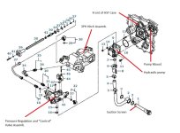
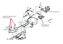
Single hydraulic pump supplies fluid to power steering (2.6 GPM), FEL controls (6.5 GPM) , and 3PH (same 6.5 GPM as FEL), return to "tank" (HST reservoir) in that sequence....

The pump and geography of front of HST housing... "Control valve" portion of pressure regulator for 3PH ...
Pump-hst-2.jpg

Control Vale and forward.jpg

Dale
 
Last edited:
   / GC1720 - Deadheading hydrostat? #30  
Koua,
One advantage to the pump being in the transmission is very short inlet line with less chance for cavitation.

Our 5000 & 5600 Fords both had the implement pump in the transmission housing. Short steel pickup tube with screen similar to car engines.

DL
Appreciate the parts diagrams. Looks like priority flow system for steering.

Now back to original concern on why the tires won稚 spin for the OP.
 

Tractor & Equipment Auctions

2014 VOLVO VNM DAY CAB (A51222)
2014 VOLVO VNM DAY...
NEW 2024 LOAD TRAIL 83IN X 14FT Tandem Axle Dump Low-pro Trailer (A51039)
NEW 2024 LOAD...
2015 KENWORTH T800 MID-ROOF SLEEPER (INOPERABLE) (A50854)
2015 KENWORTH T800...
Komatsu PC490LC-11 Hydraulic Excavator (A49346)
Komatsu PC490LC-11...
2013 VERMEER RTX1250 RIDE ON TRACTOR (A51242)
2013 VERMEER...
2012 DRAGON 130 BBL STEEL VACUUM TANK TRAILER (A50854)
2012 DRAGON 130...
 
Top