Gear Driven Hydraulic Scarifier System on Boxblade

   / Gear Driven Hydraulic Scarifier System on Boxblade
  • Thread Starter
#31  
Bird,
I figured the entire assembly including the re-inforcement for the shanks added approximately 350 lbs to the boxblade. I think the original 7 footer weighed in right at 600 lbs to start.

Surprisingly, the overall cost was not nearly as much as you would think, the hydraulic cylinder was $40 on eBay, hydraulic hose were $25 from Ag supply and the rest was scrap metal and bolts I had lying around in the garage or bought at scrap price...less than $150 and that included the backhoe subframe steel too! OK, so the retro-fit design and machining might be expensive if you hired it out, but in this case I did it all myself so it cost me nothing, except missing a few rounds of golf. It was actually really fun to build this stuff for a change! But you are right, it turned out beautiful for a tractor implement. Thanks.

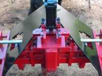
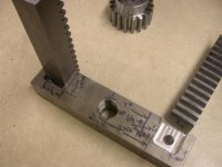
So here's a closeup that shows the back of the center bar and the support mount for the hydraulic cylinder. You can clearly see the clearance I had to cut into the boxblade brackets for the entire shaft and also when the riser bar and shanks move up. Again, the final assemble required having them on the blade while each gear set was assembled with keys. You can also see the 2 sets of bolts and clamps that hold and position the hydraulic cylinder to it's mount here.
 

Attachments

  • 868242-REAR VIEW CYL MOUNT.JPG
    868242-REAR VIEW CYL MOUNT.JPG
    69.5 KB · Views: 522
   / Gear Driven Hydraulic Scarifier System on Boxblade #32  
Wow, what a lot of work man! It is interesting, I've only seen the type with a pivot arm and cylinder to raise and lower them.
 
   / Gear Driven Hydraulic Scarifier System on Boxblade
  • Thread Starter
#33  
Mike,
You'd be surprised at my garage shop...not what you think. I've got a couple of milling machines, big lathe, surface and bench grinders, a wet saw and a TIG welder. It's very crowded but I manage meagerly in it. It's a standard 2 car garage. I do have all kinds of specialty tooling I've built over the years and many, many roll-aways and tool boxes. I still do some occasional mold work for select customers only. Just seems I'll never get rid of my personal tools. Kinda like Herpes, once you get them you never get rid of them. /forums/images/graemlins/grin.gif

The painting booth? Well if you saw those pictures and the ones about the backhoe subframe, you'd see they are painted in my driveway and also at camp, hanging from trees! My wife is just VERY good at it and she's also the photographer for all these pictures.

Here's a picture that shows some of the tool room at camp. It's a 10' x 20' enclosed canopy. This is my 10 ear old son Wesley helping to clean the paint off the gear teeth. So I've got all kinds of help too! I'll tell you what...having to drill large holes or sawing steel at camp is no picnic. Plus welding, assembly and whatever else is just plain hard on uneven ground, dirt mud and rain. But then...who would I get to do it for me? /forums/images/graemlins/confused.gif
 

Attachments

  • 868255-WES IN CAMP WORKSHOP.JPG
    868255-WES IN CAMP WORKSHOP.JPG
    93.2 KB · Views: 567
   / Gear Driven Hydraulic Scarifier System on Boxblade
  • Thread Starter
#34  
slowzuki,
You're right, me too. Those pivot ones I've seen usually have deeper boxes so the shanks can swing down into position. My boxblade was not deep enough front to back to do that, plus the top link brackets were in the way. Having that to work with, I had to retro-fit mine using this rack and gear principle. The pivot down principle is much simpler if you have the room to do it. I did get a lot of self satisfaction being able to accomplish the same thing in a different way though.

This pictures shows me trying to fit the riser bars in the rain and mud at night on my rural property. I had to pull and push them up and down hundreds of times after each time I opened the holes so they would slide freely. My back is shot now. /forums/images/graemlins/grin.gif
 

Attachments

  • 868268-FITTING AT CAMP IN RAIN.JPG
    868268-FITTING AT CAMP IN RAIN.JPG
    81.9 KB · Views: 503
   / Gear Driven Hydraulic Scarifier System on Boxblade #35  
Holy Cow Rob! I think that is a fantastic idea/design. I would love to do something like that.
 
   / Gear Driven Hydraulic Scarifier System on Boxblade #36  
Mad man. Mad man. The 7018 welds are actually pretty good, must be new or newly dried rod. I can only get welds that pretty with 6013. Maybe I need some practice.

I have a field fab question. I need to create the large, 1" or so diameter holes in barstock of 1/2" thickness plain mild steel to eliminate the side pin of the 3ph hitch and convert my hog to a captured hitch pin style. What do you recommend for drilling 1" holes in mild steel aside from a bench drill? I have a half inch drill and am considering either a big honkin drillbit or a hole saw or? I am pretty cheap and need to drill the holes on the implement.

Good to see you involved the boy. He could be a dentist with all that tooth cleaning he did.
 
   / Gear Driven Hydraulic Scarifier System on Boxblade #37  
Gee Rob,
That is a work of art /forums/images/graemlins/grin.gif Really nice job!!! I know you must have had those spur gears and racks laying around the shop, no sane person would go to that expense to change the scarifier height /forums/images/graemlins/confused.gif

Just curious what material you made your alignment pins out of ? Gonna make some covers or boots to keep the dirt out of the mechanism?

scotty
Ps Actually I would think that you could have made a drill jig to mount the alignment pins, tap the ends of those pins though drill the box blade and then weld them in position?
 
   / Gear Driven Hydraulic Scarifier System on Boxblade
  • Thread Starter
#38  
Jarrett,
There's no reason you couldn't do it. Just be sure to plan ahead when you measure up your boxblade. What i really like is the added support behind the shanks. They are welded to the boxblade itself and will not give. As opposed to the pivot type, the stress...resistance on its scarifiers is directly translated to its hydraulic cylinder and pivot point...mine is not.

This picture shows the tapped hole in the cylinder rod and lock bolt I used to set the position of the push bar on the cylinder so I could get full travel.
 

Attachments

  • 868431-TAPPED HYD ROD.JPG
    868431-TAPPED HYD ROD.JPG
    41.7 KB · Views: 447
   / Gear Driven Hydraulic Scarifier System on Boxblade
  • Thread Starter
#39  
Highbeam,
I would try the hole saw because there is no easy way to drill that big with killing your self or blowing up your drill motor. The key is to run whatever you use for that sixe at very low rpms. If there's a way to get those holes into the barstock while off the tractor in a shop with a milling machine, that would be better yet. But if you can't, I'd try the hole saw and bring some spares in case.

Here's a picture of the hydraulic cylinder bar that holds the racks that activate the system. I pocketed the position of the racks to match up the gear locations.
 

Attachments

  • 868437-HYD RACK CARRIER.JPG
    868437-HYD RACK CARRIER.JPG
    53.9 KB · Views: 449
   / Gear Driven Hydraulic Scarifier System on Boxblade
  • Thread Starter
#40  
scott,
Unfortunately all the spare gears I had were not 6 pitch I wanted so I bought them. I probably should have form ground an involute cutter and machined them up from bar stock using my old dividing head like the old days. But I had my plate full knowing I'd only have one week of vacation to finish this project and the backhoe subframe.

As far as making a drill jig then drilling and tapping the rods and screwing them on location I thought about doing that.
I know you're a tool maker too so you know that the threads have clearance in them to start with unless they're like class 3A or something and I would not use that for this project. Don't even know if I could have tapped them straight anyway without a tap guide? Second is that the surface the guide pins screwed to is not close to flat and parallel unless I surface ground the boxblade. Most important and most unpredictable is whenever you add weld, even to a screwed alignment pin, it's gonna suck off from being perfectly perpendicular to the surace. This is just some phenomena of the real world in all the years I've been doing this. And that's exactly the main problem I faced was loss of perpendicularity when I welded them...not so much center to center. As you can see from a previous picture, I fixtured the guide pins inside the lifter bars before welding them. To my surprise, the stayed pretty good that way but bent over after each weld pass.

The guide pins themselves are ejector pins that I use in mold making. They have a pre-hardend core of about 36Rc and the outside is a nitrided surface about 65 Rc.

In this picture you can see how I went about positioning the guide pins inside the lift bars before welding. This gave surprisingly good centers but the guide pins still moved and bent from the 2000° welding heat. Keep in mind that the pins are exactly Ø.9995 and the reamed holes are Ø1.0005. If all but one were perfectly aligned and parallel, it would bind up. So I was really lucky to have it come out this good. Heck, I've had guys on my horizontal boring mills do pin and bushing work that did not come out this good at times. /forums/images/graemlins/grin.gif
 

Attachments

  • 868472-LIFT BAR LINE UP.JPG
    868472-LIFT BAR LINE UP.JPG
    86.8 KB · Views: 454

Tractor & Equipment Auctions

Hay Fork (A50860)
Hay Fork (A50860)
2025 K2223 UNUSED Double Garage Metal Shed (A50860)
2025 K2223 UNUSED...
BREWSTER DRAWWORKS WITH TWIN CATERPILLAR ENGINES (A50854)
BREWSTER DRAWWORKS...
2007 TROXELL KILL/TRANSPORT TRAILER (A50854)
2007 TROXELL...
2013 VERMEER RTX1250 RIDE ON TRACTOR (A51242)
2013 VERMEER...
1993 Harsh Feed Mixer (A51039)
1993 Harsh Feed...
 
Top