Argonne
Gold Member
- Joined
- May 21, 2005
- Messages
- 282
- Location
- Paris, TX
- Tractor
- JD2210, Ford 4400, Case IH 685, Terramite T7, JD 6x4 M-Gator
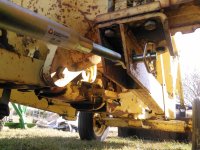
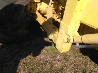
My Ford 4400 came without stabilizer arms, and I have been getting along without them until now. I finally picked up a couple of thread/adjustable ones at TSC and installed them, so far so good. However, when I lift the hitch, the arms bind within a few inches threatening to break something.
This is not surprising since the tractor-end stabilizer bar pins are at a slightly different axis than the lift arm shaft.
I am obviously doing something wrong, and I hope you guys can look at the pic and point out what it is.
Yea, I could just install one and let it slew during lift (no big deal with the mower), but with other implements like the trailer spotter, it would be undesirable. My OCD wouldn't like it either ;-) .