Radair
Thanks for the feedback.
The way I look at it the rafter is sitting on top of the plate and the ridge beam. The x-sec is the area above each notch or 18.5 sq in. above the plate & 16 sq in. above the beam. OK, the plate does have a little more x-sec area above it.
I thought about wood gussets and the notch splitting. Sometimes when you get off the beaten path it’s hard to know where the line is. Anyway, it would be simple to add the gussets in now.
Johnday
Since the ridge beam is supported at each end the rafters only see simple gravity loads. Collar ties and ceiling joist are not necessary. This is a standard principle used for cathedral ceilings.
The beam does deflect slightly under load. My calculations indicated about 0.3” with dead load, and another 0.5” under full snow load. After I got the roof installed the actual deflection was only 0.2”. Since the beam had about this much crown, it’s just about flat right now. If we ever get a worst-case snow level I’ll be able to check the live load deflection.
All the rafters are tied together with a hurricane strap on top and a mending plate on the side. Look closer at some of my pictures.
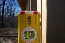
The walls are plumb (see attachment)
Henro
One of the reasons behind the I-beam is so I can lift things with a dolly mounted on the lower flange. If I put ties across I couldn’t pick-up my tractor in one stall and move it to the adjacent ones /forums/images/graemlins/grin.gif
Inspector507
The steel I-beam does deflect as indicated above. The big difference is this beam has structural columns supporting it at each end. In a normal roof the ridge is not structurally supported and the roof loads want to flatten out the rafters that in turn push out the walls. To keep this from happening you need either collar ties, ceiling joists or both. To get the roof load translated over to the eave plates the rafters go into compression and the collar ties/ceiling joist are in tension. Once you support the ridge beam, it now directly holds 1/2 the load and the eave plates the other 1/2. All the forces are straight down.
All – I appreciate the feedback. I’m not sure if I mentioned it but this building is my prototype for my next one. Obviously I want to improve the rafter connection to the I-beam. I’m leaning towards a welded on connector to eliminate notching the plumb cut and to provide attachment to the beam. Hard to find information about this kind of stuff for the DIY’er.
This first building is just really a 3-vechicle garage. I wanted a nice open ceiling, no trusses, joists, or collar ties. The only way to achieve this was to use a supported ridge beam. With a 34’ span steel became the cheapest material. The beam ($465), rafters ($780) and columns ($305) totaled $1550. That’s about the same as using trusses. A regular design with collar ties would have been much cheaper. Having the open cathedral ceiling is really cool; having that I-beam is even better. I can now pop the boat off the trailer or pull my motor.
As soon as I button up this building I’ll be starting on my workshop. It’s L shape with a double car garage area (for big projects) adjacent to the workshop. Total area is 1664 sq ft. Again, I want the nice open ceiling with the I-beam for lifting and moving things around.