This post if half question and half statement, but I see in thread after thread on here discussions of HST's and comparing them to automatics and people talking about the infinitely variable speed. Never once have I heard mention that there is actually a minimum speed at which full torque is available even with an HST (at least on my Kioti CK20HST). The question part is... is that behavior unique to Kioti? It is also possible that due to this, just like with a gear tractor, the combination of needed speed and needed torque could be impossible, even with an HST tractor that otherwise has enough oomph. It just may not have enough at a slow enough speed or high enough speed, albeit this is probably much less likely than with a geared tractor.
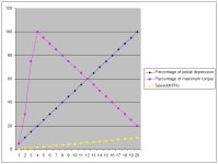
Using my CK20HST for example (and I have no idea if this same effect is reproducible on other brands or if it is specific to the Kioti CK20): If I slowly start pushing forward on the HST pedal, the torque and speed BOTH build up to about 20% of pedal depression (due to going from no hydraulic flow through the tranny up to the valve being 100% open at about 20% pedal depression). Then after the flow has reached maximum, then normal HST tranny physics are at work just as you guys talk about. See the graph that I made purely with fudged numbers, but just to explain the effect that I see, and that was also described to my by the dealer.
In effect, even HST, or at least MY HST does in fact have a minimum speed at which full torque can be applied... are all of them like this? I suspect so since I can't imagine any way around it.