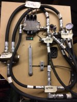
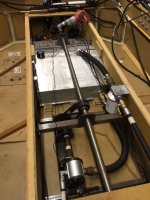
These are pictures of the valve control panel and also of the pump, tank, filter etc. I have chucked a drill motor onto the drive shaft to spin the pump and circulate oil into the system. The control panel shows the three cylinder valves, the two motor valves, flow divider, and inlet and return hoses.
I think I may have made a basic mistake by having the cylinder valves inlet T into the inlet side of one of the motor valves. If the motor valve is in neutral does the oil flow directly through the valve to the return hose and there is no oil pressure, or flow, to operator the cylinder valves?
FWIW I don't expect to ever have a reason to operate the cylinders and the motors at the same time.