Hydraulic Question on Homemade Post Driver

   / Hydraulic Question on Homemade Post Driver #1  

Whfabrication

New member
Joined
May 20, 2019
Messages
8
Location
Pennsylvania
Tractor
Mahindra 4010
Well I am new here and I could use some help on a hydraulic circuit I'm attempting to hook up and currently having difficulties for some reason. I'll try and get all the information in here with keeping it short.

I've read quite a bit on here about hooking into the power beyond and though I had a decent understanding of hooking it up but it looks like I was mistaken. I'm working on a post driver with a double acting cylinder that moves an arm with pulleys on it to lift a 400 lb weight up the mast (protech style). After hooking up all the hydraulics in the way that I though was correct and began testing this is what Ive came up.

After running the tractor and moving the valve a few dozen times to try and get the cylinder to move (which it didn't) I though I should have bleed the system so I at that point cracked both lines at the cylinder and moved the valve in one direction again until it seemed as if it were just fluid coming out then I switched to do the other line after tightening the first.

Eventually I got to the point that the cylinder would extend if I only slightly pulled on the valve but when I went to retract the cylinder I would have to pull the valve the whole way and release to spring center about a dozen times to get the cylinder to inch its way closed. Then I tried having someone slightly raise the FEL while I was operating the valve on the post driver which somehow made the cylinder act much more normal extending and retracting at a higher rate of speed and I didn't have to be so careful on the valve to get it to move.

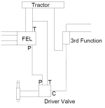
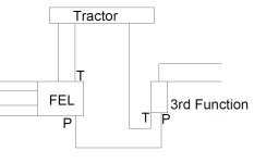
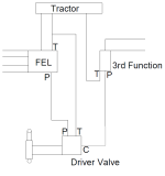
So Ive attached a hydraulic diagram of how I have the unit plumbed, and here is a list of items that make up the hydraulic diagram.

2012 Mahindra 4010 online claims 8.3 GPM
BESKO 8625-300-500-2 Loader Valve
8GPM Wolverine MB1185C1 Post Driver Valve with PB Plug installed
WR Long Inc 3rd Function Solenoid Valve
8 DA Wolverine Cylinder
All hydraulic lines are 1/2
3 Quick Connect Lines at the rear of the tractor ( Power Beyond out, Power Beyond in, Tank)

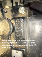
Do I have the P and C ports reversed on the driver valve even though I believe I followed there instructions correctly? The labels I have on the attachment are the only ones that I've found labeled on the FEL valve.

Any insight to my issues would be great
Thanks
IMG_3504.jpg
Hyd Plumbing.png
 
   / Hydraulic Question on Homemade Post Driver #2  
The in line to your new valve should be connected to the power beyond on the loader. There would have been a line to the 3rd function there before (or 3pt if there's no 3rd function).
The new valve's PB port would then go to the 3rd function's in port.

It sounds like maybe the new valve's in port is connected to the loader's tank port? That tank port should only see pressure (and not much at that) when you move the loader.

Your diagram has the loader P port connected to the new valve's P port. If P means power beyond that would be wrong.... PB is an output.
 
   / Hydraulic Question on Homemade Post Driver
  • Thread Starter
#3  
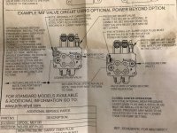
Thanks for the input, yeah I though that P was the power to the next function but looking at the diagram that came with the new valve and after checking on line at prince hydraulics site they claim P is the inlet for this valve and "C" is the power beyond flow.

I went out and looked at all the lines again to verify that the new valve's in port was not hooked the loaders tank port. I've attached some more picture of the labels on the valves.

Here is how the loader valve was originally hooked to the 3rd function before I did anything to the hydraulics.
IMG_2870.jpg

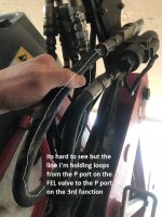
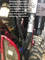
Here is what I have now for lines, the Yellow comes from the P port on the loader valve and goes to the new valve P. Then the C port from the new valve comes back and goes to the P port on the 3rd function.
IMG_3499.jpg

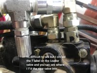
Here is what I found may be the issue but I'm not sure exactly sure how to test. Maybe with a pressure gauge? If you look at the first image you'll see the 2 ports labeled on the 3rd function as P and T. I hooked my C port from the new valve to the P port on the 3rd function but then the T on the 3rd function goes back into one of the hard lines directly into the tractor. Then the FEL valve has a T label on it and I hooked my T port on the new valve into that line.... Shouldn't the 3rd function be fed with the power beyond and then go to the next circuit which originally would have been the 3 pt? That block being labeled T makes me slightly confused with this set up now.
IMG_2869.jpg
IMG_3497.jpg

Here are the original and updated hydraulic diagrams. I added the labeling on the 3rd function block as to what they have them labeled and how they run on the tractor.
Original Hyd Diagram.jpg
Updated Hyd Plumbing.png

Thanks again for the help
 
   / Hydraulic Question on Homemade Post Driver #4  
Port labelling does not seem to be consistent across manufacturers.

The third function may well have power beyond and tank combined. That's common.

Your diagram looks correct to my understanding. Maybe go back and check all the valve's port labelling and that your connections are on the right ports?

When the loader is moving there's less (or nothing) coming out it's power beyond, and flow out it's tank port. Since the post driver moves a little if you move the valve the right way when the loader is not moving, I wonder if the problem is on the outlet side of the post driver valve... like it's going out to a line with flow/pressure in it.
 
   / Hydraulic Question on Homemade Post Driver #5  
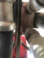
4th picture: Right fitting is the PB port or Carry over port, hence the C labeled right below the circle you draw. Left port is the tank port.
 
   / Hydraulic Question on Homemade Post Driver #6  
whfab,
For this to work properly you need to connect the valves in series. The "C" port on the FEL valve should connect to the "P" port of the next valve. Then the power beyond from that valve goes to the "P" of the next valve. The power beyond of the last valve then supplied oil to the 3 point hitch. teeing into the "P" port of the FEL valve will not work with open center fixed displacement pump systems.

NOTE: The 3rd function D03 valve the "T port is your power beyond port.

Hope this makes sense
 
   / Hydraulic Question on Homemade Post Driver
  • Thread Starter
#8  
Ok I got some more pictures of where on the actual tractor these lines go from the FEL valve. I also called the local dealer to try and get labeling for this valve but he cant get that information from what they give him.

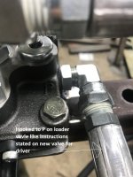
Here is a better pic of the side of the valve labeling where the T port is labeled. The "C" in question actually is the O in the brand name Brasko.
IMG_3509.jpg

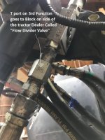
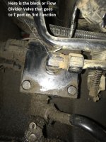
The first picture of line location is from the T port on the 3rd function, it goes to a block about midway down the rear axle assembly. When I talked to the dealer he called the block on the side of the tractor a Flow Divider Valve. This line would have originally went to the P port of the FEL valve.
IMG_3513.jpg
IMG_3512.jpg

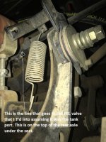
Next its hard to see but the line that I T'd into that looks to be labeled with a T on the FEL Valve goes to the back of the tractor and goes into the top of the rear axle assembly under the rear seat.
IMG_3521.jpg

And finally the line that from what I can tell is unlabeled that is next to the line I T'd into goes to the side of the axle assembly in front of the block or Flow Divider Valve. This port is slightly behind and up from where the hydraulic filter is on this tractor which is accessed from underneath.
IMG_3511.jpg

I hope this helps some because I'm not completely sure what to think. Should I still try switching my tank line to the port that goes to the front most line on the last picture I posted here?
 
   / Hydraulic Question on Homemade Post Driver #9  
Besko. They make the loader valve on my Branson too. On it the PB port does not get flow when the loader is moving, it all goes to the tank.
On my Branson the tank line from the loader and the PB both disappear under the tractor and go back to the transmission. The tank line goes into the transmission under the seat. But it could go anywhere in the transmission. The PB would go straight into the very back of the transmission where the 3pt is but on my tractor there's SCVs and backhoe connections in the loop first.

I though the 4th pic on your earlier post that shows the tee on the tank line was your added new valve, not the loader valve.

I still think that you've hooked the new valve up wrong. It's always possible that it's defective from the factory but that's rare.
 
   / Hydraulic Question on Homemade Post Driver
  • Thread Starter
#10  
Yeah I don't know what I was thinking when I typed Brasko. I'll probably try moving my new tank line over one port on the FEL vavle to where the line goes into the transmission near the filter like pstg mentioned earlier but it'll be this weekend until I have time to get to that.

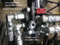
No every picture I've posted so far has been of the Besko valve. The new valve is labeled very clear with P for pressure in, T for tank, and C for carry over or power beyond. Here are pictures of the new valve.
IMG_3500.jpg
IMG_3502.jpg
 

Tractor & Equipment Auctions

2007 FORD F-450 SUPER DUTY (A52472)
2007 FORD F-450...
2005 Chevrolet Trailblazer EXT 4X4 SUV (A51694)
2005 Chevrolet...
2022 CHEVROLET 2500HD CREW CAB TRUCK (A51406)
2022 CHEVROLET...
2019 FORD F-150 XL SINGLE CAB TRUCK (A51406)
2019 FORD F-150 XL...
2011 JOHN DEERE 6115D (A52472)
2011 JOHN DEERE...
2018 DandA 220V Hydraulic Breaker Excavator Attachment (A51691)
2018 DandA 220V...
 
Top