Hydronic heat, I broke it.

   / Hydronic heat, I broke it. #41  
Yes it would be the right way but it would require disassembling that main loop of old 1 1/2"pipe cutting and threading it adding two flow tee's.
With luck adding an air vent to the new #3 or 2b possibly on both sides may get flow established again.

I agree on the relative ease of this plan, and am optimistic that the result will be satisfactory.
 
   / Hydronic heat, I broke it. #43  
I split radiator 2 into radiator 2a and radiator 2b.

Just curious, how did you split one radiator into two? And if you did, how did you plumb them back together?
 
   / Hydronic heat, I broke it. #44  
:laughing::laughing: Yeah, if I interpret your interpretation of my interpretation of the as-built system - you are correct in your head scratching. The system is a one-pipe main, so the circuit tee-s off to a radiator, through the radiator, and back down to the SAME main pipe.

Picture me when we first moved in - laying on my back in the dirt with a flashlight trying to figure it out - why is the radiator "in and out" going to the same pipe?

Also agree about the air valve - I don't know why it has an air valve UNDER the house. I replaced the original manual bleed with a an automatic thingy a couple of years ago.

Anyway, it all worked fine until I added that U shaped section.

In a closed system, like hydronics, the air has nowhere to go except to accumulate at high points or at the air separator and/or the expansion tank, if you have a one. Diaphragm expansions do not trap air. Air is can be your biggest gremlin on these systems. I have been assuming you have fin pipe convection panel and not cast iron radiators. They create more problems being usually from converted steam systems. Usually at the beginning of air entrapment you can hear gurgling in the heating units. You need an on site diagnostician, in my humble opinion.

Ron
 
   / Hydronic heat, I broke it. #45  
You can almost never simply open a closed system, let in a bunch of air, and then expect it to purge itself simply by operating the pump. It just doesn't work in most cases. The best policy is to flush the air out with either a garden hose, or the fill valve. This is done by adding a ball vale with a hose bib on each side of it, or some variation of this idea. The flushing water comes in after the ball valve, goes clear through the loops, and then is expelled through the bib right before the ball valve. This flushes the entire system until the majority of the air is purged. Then the air vent will take care of the rest of the air, over time. All venting can be done at the boiler, most of the time. All you have to do is get enough air out the the circulator can pump reliably, then let the vent do the rest. Normally, only one vent is needed, and it is often best at or near the boiler.

Simply adding a vent at the hight point will only help if the air can get to it, and if it is on a separate loop form where you were working, likely it will do nothing.

One of your drawings showed a vent at the low point in the system. The vent should be where all the water goes by it, near the boiler, or at the top if you can't purge it out properly.

Water in a closed loop is not affected by up or down in the pipe. But air will try to accumulate at the top. Normal circulation rates are enough to push water down to the boiler, as it cannot trickle up through the water faster than the down velocity of the flow. But the pump will not pump air.

When starting the system after air has been admitted, it's best to purge it, as I mentioned, and then let it circulate until the air is vented.

Air can only accumulate in an expansion tank if it is an open style with no diaphragm. Modern systems use diaphragm tanks. Older ones use open tanks. I used an open style on mine because they are usually less trouble in the long run.
 
   / Hydronic heat, I broke it. #46  

A saddle tee will not work on a one pipe system, what is required are flow tee's;

Legend Monoflow Tees for Hydronic Heating Systems. Legend Monflow tee

The existing system is using flow tee's or it would not have worked, they can develope about 1 or 1.2 pounds of differential double that if two are installed.
1 psi equals about 27 inches of water lift capability, once all the air has been eliminated from the loops very little differential is required to maintain flow as the rise and falls will cancel out much of the differential required to establish the flow.

Thermal dynamics have been attempted in the past as the hotter water should rise and the cooler should fall, unfortunately that often results in two phase flow in just the risers,
water will actually flow up in the center of a pipe and then also flow down on the outer edge of the same pipe in a thermal loop.
 
   / Hydronic heat, I broke it. #47  
This armchair diagnostics is getting poor WF more confused and I am probably part of the problem. I should never have responded without seeing the system. WF, I apologize if I have.

Old systems are not always the easiest. The industry has learned a lot. The post recommending flowing water through the system makes sense. Then you have an open system with an escape route for the air; like our hydraulic systems draining to open to atmosphere tank. Important Questions are:

What type expansion tank; air cushion or diaphragm?

Where is it locate?

Is there an air eliminator (not a vent) at the top of the boiler ahead of the expansion tank?

Do the existing and/or new air vents have an accumulation space (chamber) as opposed to just a valve or petcock?

Are you getting any air from the vent points?

Pictures would help a lot more than diagrams. Both at the convectors (proper term for fin pipe) and the boiler room.

Ron
 
   / Hydronic heat, I broke it. #48  
When designing these systems there are many considerations. When servicing them, or altering them, you have to deal with the decisions that were made by others in the past.

When looking at general schematics from engineers and manufacturers, you'll find they tend to always put in valves and equipment that will allow for any problems, work in any situation, etc. Usually this generic design process makes things much more expensive and complicated. It allows you to tune out problems that were introduced in other ways and should not be there in the first place. Many parts can be left out, and should be left out. Beauty and efficiency come from simplicity, not over the top rule following and ten times too many parts.

Remember, in a closed loop hydronic heating system, once it is done, when it is operating, and all the air is out, there is no use for air vents, purging valves, air scoops, etc. They are all there to get you started. So try to do your initial air management in the simplest way you can. Air only rises to the top if there is no other force to keep it form doing so. Elevation of the pipes, ups and downs, mean nothing to a closed loop system with no air in it. Water velocity will move air to wherever you want it to go, up or down. Water velocity, momentum, noise and temperature can all play into your game of determining what is going on and making the system perform.

Use your zero pressure change point to help you with pumping, system pressure control, bubble size and boiler character. System static head, combined with pump head must be considered when deciding on vent locations. Otherwise air venting can be a problem. It's not sufficient to simply say "put a vent at the top". In fact, that is generally not correct.

Try to design it to allow for good servicing and easy startup, while being as simple as possible. Simplicity is beautiful and does not detract from function. It adds to function, makes installation easier and reduces cost. But it is difficult to learn to do.
 
   / Hydronic heat, I broke it.
  • Thread Starter
#49  
Success!

I tried the easy fix, and it appears to have worked. All of the radiators are providing heat.

I added a vent on each end of radiator 2b.
I changed the output of 2b to 3/4
I added a slight rise to the u-trap.

During the bleeding, I noticed that the vent at the input to radiator 2b let out copious amounts of air when combined with the others.

What remains to be seen - will the system remain stable and not trap air, causing an airlock.

My hero - Rube Goldberg – Home of the Official Rube Goldberg Machine Contests

hyd889.jpg
 
   / Hydronic heat, I broke it.
  • Thread Starter
#50  
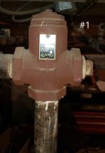
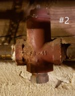
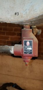
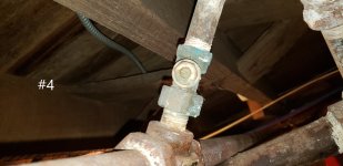
If you could, please identify the items in the attached pics.
What are they, and what do I do with them?

No problem if they need to be seen in context of where they are installed in the system, let me know.

flow.jpg
inline.jpg
Airtrol.jpg
inline b2.jpg
 

Tractor & Equipment Auctions

1985 Eager Beaver 9D0W Tri-axle Flatbed Equipment Trailer (A50323)
1985 Eager Beaver...
2014 Dodge Charger Sedan (A50324)
2014 Dodge Charger...
2022 PETERBILT 389 MID-ROOF SLEEPER (A52472)
2022 PETERBILT 389...
Adams Load Out Conveyor - Stainless Steel Assembly - Baldor Electric Motor (A52748)
Adams Load Out...
(5) Roll up Doors (A50121)
(5) Roll up Doors...
2025 25ft 1 Gauge 800 Amp Booster Cables (A50323)
2025 25ft 1 Gauge...
 
Top