JD 2510 question 3 PT

   / JD 2510 question 3 PT #1  

Temp97

Bronze Member
Joined
Jul 10, 2006
Messages
89
Location
Western New York
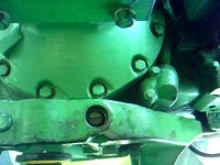
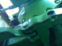
I know this is tough without pics but I'll try to describe it and later after work upload photos if needed. In front of the shaft that the 3 pt arms are attached to there appears to be another shaft that oil has blown out of one side. Thinking that this shaft is some short of self adjusting/float control for the 3 pt system. The end of this shaft is different looking. If you google AR 90082 it shows what the end looks like. It's called a lift arm latch. This looks similiar to the cover we took off. Question is, what does this shaft do and how do we get it out??? Seems like it goes all the thru and no retaining rings holding it in,

Thanks, Sarge97
 
   / JD 2510 question 3 PT #2  
Is the 2510 in question a high crop model?? If not it has the incorrect 3pt draft arms. The AR90082 is a latch that one pulls up to allow the draft arm to extend to facilitate easier attachment of 3 pt implements. Photo below is the only photo listed in 2510 parts catalog with the part number AR90082(parts key #28).
 

Attachments

  • R11993_________UN01JAN94.gif
    R11993_________UN01JAN94.gif
    17.4 KB · Views: 184
   / JD 2510 question 3 PT
  • Thread Starter
#3  
Not a high crop, If it works There should be pictures attached. 1st pic is you can see the opening to the shaft with the odd shaped end. 2nd pic is a different angle. 3rd is a view of the pin from the underside that appears to go into the center of where the shaft goes thru. 4th shows the opening and a view of where the lift arms attach. Question how to get that shaft out??? Does that pin have to come out and how?? Don't even know forsure what this shaft does.

Thanks
 

Attachments

  • IMAG0313.jpg
    IMAG0313.jpg
    45 KB · Views: 138
  • IMAG0314.jpg
    IMAG0314.jpg
    52.1 KB · Views: 148
  • IMAG0315.jpg
    IMAG0315.jpg
    215.1 KB · Views: 135
  • IMAG0316.jpg
    IMAG0316.jpg
    284.4 KB · Views: 145
   / JD 2510 question 3 PT #4  
I think from your photos you're actually referring to the L/D shaft not the AR90082. To R&R seals one must drain trans/hyd oil,support drawbar support,remove end caps and drive shaft out either side and R&R seals. Check shaft for wear,upon re-installation of parts, shim drawbar support side to side motion out and you're good to go after reinstalling oil.
 

Attachments

  • R3649__________UN01JAN94.gif
    R3649__________UN01JAN94.gif
    8.2 KB · Views: 141
  • R13471_________UN01JAN94.gif
    R13471_________UN01JAN94.gif
    11.8 KB · Views: 161
Last edited:
   / JD 2510 question 3 PT
  • Thread Starter
#5  
Thanks, What about the pin in the center (#20 on your picture), does that have to come out???
 
   / JD 2510 question 3 PT #6  
#20 stays in just #16 plus seals requires removal. Be sure and put L/D control lever under the seat in "D" before removing #16.
 
   / JD 2510 question 3 PT
  • Thread Starter
#7  
Thanks TX JIM we'll give a go and let you know soon.
 
   / JD 2510 question 3 PT
  • Thread Starter
#8  
You were right, it was as simple as driving it out. Wouldn't have known to put the lever in the "D" position so thanks for that. 2 seals, $15 a piece, fairly cheap fix. Again thanks for the help,

Temp 97
 

Tractor & Equipment Auctions

2021 Chevrolet Tahoe FL SUV (A44572)
2021 Chevrolet...
More info coming soon! (A44572)
More info coming...
2017 Ford Explorer AWD SUV (A44572)
2017 Ford Explorer...
2017 Ford F-550 Reading Service Truck (A44571)
2017 Ford F-550...
2015 Ford F-150 Ext. Cab Pickup Truck (A44572)
2015 Ford F-150...
Ariens Precision V2 Hydrostatic Lawn Mower (A44391)
Ariens Precision...
 
Top