You are using an out of date browser. It may not display this or other websites correctly.
You should upgrade or use an alternative browser.
You should upgrade or use an alternative browser.
JD6410 wiring for Rotary light switch
- Thread starter sablerock
- Start date
- Views: 29124
-
- Tags
- john deere 6410
More options
Who Replied?
/ JD6410 wiring for Rotary light switch
#1
Zebrafive
Super Member
To add, B is protected by fuse F104 30Amp
Re: JD6410 wiring for Rotary light switch/ fuse box layout
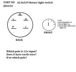
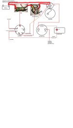
I have tested the switch. see new picture.
Not sure how to wire pole H.
Does anyone have the Fuse box complete legend?
Is it impossible to get wiring diagram for this tractor?
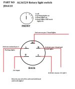
I have tested the switch. see new picture.
Not sure how to wire pole H.
Does anyone have the Fuse box complete legend?
Is it impossible to get wiring diagram for this tractor?
Attachments
Zebrafive
Super Member
Re: JD6410 wiring for Rotary light switch/ fuse box layout
Wire H goes to splice, from there it goes to the front grill work lights, the work light relay K106? and headlight relay K107.
Wiring diagram is contained in the TM (tech Manual) which TM depends on where your machine was built for (country or region) maybe serial number too?
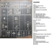
I will try and ID what I can for the Fuse Box. F = Fuse, K = Relay, V = Diode. If BLANK it was not used this machine.
F= Fuse
F101 Main fuse battery wire to key switch
F102 ELX = Electronics
F104 Hazard lights
F105 Turn signals, Air Seat ?
F106 PTO, Diff lock, FWD
F107 Headlight switch wire B
F108 Left taillight
F109 Right taillight
F110 Left low beam
F111 Right low beam
F114 Work light????
F115 Calibrate HCU (Hitch Control Unit) DO NOT PUT A FUSE HERE !!!!! IT will UNCALIBRATE YOUR HCU!!!!!!!!
F116 Instrument lights, HCU Hitch Control Unit
F119 Fuel heater, rear power outlet
V = Diode. Tells you what circuit it is for, if blank, not used.
V104 hi/low beams
V105 Electronics
K = Relay
K101 Electronics
K102 Accessories
K103 Don't know
K104 not used
K105 Fuel heater, Power outlet
K106 Work lights?
K107 Lights hi/low beam Not sure what ECE means
K108 not used
K109 FWD
K110 Diff lock
K112 PTO could be front or rear
K113 PTO could be front or rear, not sure
I am not sure if the first relay (K112) will be rear PTO, and the second (K113) front PTO, or the opposite.
Hope this helps.
I have tested the switch. see new picture.
Not sure how to wire pole H.
Does anyone have the Fuse box complete legend?
Is it impossible to get wiring diagram for this tractor?
Wire H goes to splice, from there it goes to the front grill work lights, the work light relay K106? and headlight relay K107.
Wiring diagram is contained in the TM (tech Manual) which TM depends on where your machine was built for (country or region) maybe serial number too?
I will try and ID what I can for the Fuse Box. F = Fuse, K = Relay, V = Diode. If BLANK it was not used this machine.
F= Fuse
F101 Main fuse battery wire to key switch
F102 ELX = Electronics
F104 Hazard lights
F105 Turn signals, Air Seat ?
F106 PTO, Diff lock, FWD
F107 Headlight switch wire B
F108 Left taillight
F109 Right taillight
F110 Left low beam
F111 Right low beam
F114 Work light????
F115 Calibrate HCU (Hitch Control Unit) DO NOT PUT A FUSE HERE !!!!! IT will UNCALIBRATE YOUR HCU!!!!!!!!
F116 Instrument lights, HCU Hitch Control Unit
F119 Fuel heater, rear power outlet
V = Diode. Tells you what circuit it is for, if blank, not used.
V104 hi/low beams
V105 Electronics
K = Relay
K101 Electronics
K102 Accessories
K103 Don't know
K104 not used
K105 Fuel heater, Power outlet
K106 Work lights?
K107 Lights hi/low beam Not sure what ECE means
K108 not used
K109 FWD
K110 Diff lock
K112 PTO could be front or rear
K113 PTO could be front or rear, not sure
I am not sure if the first relay (K112) will be rear PTO, and the second (K113) front PTO, or the opposite.
Hope this helps.
Zebrafive
Super Member
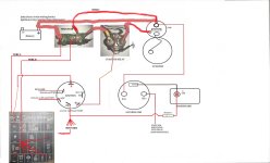
Fuse could be main fuse, or fuse for cold start aid ( heater grid in air intake)
Starter relay may be cold start aid relay, wires look small for starter??? But not sure.
If for starter One small wire is from key switch (might be marked S) and other small wire is ground.
Larger studs, one from battery after main fuse and one to starter.
If for cold start aid, one small from key switch, one small to ground. One large to battery, other large to heater grid.
Is the tractor Cab or Open? Do you know if it's for North America or European markets?
Wiring is very complicated for these, I would try and get a TM (Tech Manual) You need "operations and tests" NOT "repair" for electrical diagrams.
Does ignition switch drawing match what you have? Does not look right. It should have two battery feeds and a ground feed.
You may want to see if you can buy wiring harnesses from a tractor salvage yard.
Its European, 2-post ,no cab.
That fuse is the main fuse..the cold start aid has got its own relay and fuse(Disconnected, not needed).
The ignition is Japanese replacement part.
Nobody here wants to help with Tech Manual.
Salvage yards no can help.
You eat an Elephant small bites at a time.
If you can OK my latest drawing ,then one bite done.
With your help, I am only going to wire the essentials like: FWD/DIFFLOCK/PTO SWITCHES/SOLENOIDS and maybe HEADLIGHTS/WORK LIGHTS
Attachments
Zebrafive
Super Member
Its European, 2-post ,no cab.
That fuse is the main fuse..the cold start aid has got its own relay and fuse(Disconnected, not needed).
The ignition is Japanese replacement part.
Nobody here wants to help with Tech Manual.
Salvage yards no can help.
You eat an Elephant small bites at a time.
If you can OK my latest drawing ,then one bite done.
With your help, I am only going to wire the essentials like: FWD/DIFFLOCK/PTO SWITCHES/SOLENOIDS and maybe HEADLIGHTS/WORK LIGHTS
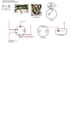
You need to change this drawing.
Top Stud of starter: Three wires:
Go from the battery to top large stud of the starter.
Also on top large stud of starter go to alternator.
Then third wire from top starter stud to main fuse (side with two wires)
Main Fuse:
Side with two wires:
One comes from top stud of starter (see above)
Second goes to large stud of starter solenoid
One wire side:
Goes to power fuse Box, from fuse box F101 goes to Key (Ignition) switch
Starter solenoid
One large stud wire from main fuse (two wire battery side of fuse) see above
Second large stud goes to Lower large stud starter
One small stud comes from ST (start) of key switch (goes from key switch, to a neutral switch, then to starter solenoid)
Other small stud goes to ground.
Zebrafive
Super Member
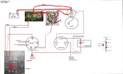
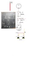
drawing updated. Some questions:
1. why extra WIRE C ?
2. CAN 6v led function as a warning light and is it correctly wired?
3. why not take WIRE A from point B on main fuse?
Thats about it. I am ready to begin!
1. You need to remove your wire shown from battery to Main Fuse A. Then wire C feeds Main Fuse. The way you have it labeled (Main Fuse) , flow for Main Fuse will be in (wire C) at B and then out at A.
2. Is this an Alternator warning light? I am not sure, but think if it is wired so it lights when current flows from key switch towards the alternator it should work. LEDs have a certain direction for current flow that they will light, other way they will not light.
3. Both wire A & B, to Fuse Box should come off A of Main fuse. Flow is Battery to starter. Starter to Main Fuse B (wire C). Though Main Fuse and out of Main Fuse at A.
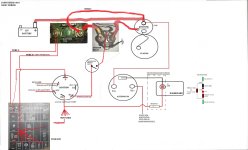
Ok, version 3 done.
Yes its the alternator warning lamp.
I understand it has 2 main functions:
1. to "excite" the alternator before starting
2. act as warning device when alternator is showing signs of failure.
My main concern is, will LED "flicker" when alternator shows early signs of failing?
What about an overcharge?
Attachments
Zebrafive
Super Member
Corrected drawing looks good.
I am not sure about the LED. Normally a std light bulb is used. It lights when the key is ON but engine not running. Goes out when alternator voltage exceeds battery voltage. The battery voltage > < alternator voltage oppose each other. If the light come on when running, it means the alternator is not producing more voltage than the battery. It does not indicate overcharge.
I am not sure about the LED. Normally a std light bulb is used. It lights when the key is ON but engine not running. Goes out when alternator voltage exceeds battery voltage. The battery voltage > < alternator voltage oppose each other. If the light come on when running, it means the alternator is not producing more voltage than the battery. It does not indicate overcharge.
Great! one "schematic" ok.
I am going to revert back to 12v pilot bulb. Much safer and easier!
I want to thank you for your inputs.
The next schematic will be for lights/work lights.(another small bite).
Are you willing to collaborate?
Albert
I am going to revert back to 12v pilot bulb. Much safer and easier!
I want to thank you for your inputs.
The next schematic will be for lights/work lights.(another small bite).
Are you willing to collaborate?
Albert
Zebrafive
Super Member
I'll try and help it should be easier.
Please make a list of what lights and where they are located. I've seen work lights on the front grill (sides by head lights), front on fenders and rear on fenders. Also if you have separate switches for any of the lights.
Please make a list of what lights and where they are located. I've seen work lights on the front grill (sides by head lights), front on fenders and rear on fenders. Also if you have separate switches for any of the lights.
I found the neutral start switch on transmission and it still works.
Pls check my latest diagram for its wiring.
I see you have posted a partial SCHEMATIC on thread "JON DEERE 6410 WONT START" on 23 June 2015, by member WEEZY22.
Where did you get it? Do you have the rest?
I will make complete list of lights and other components before we start.
Pls check my latest diagram for its wiring.
I see you have posted a partial SCHEMATIC on thread "JON DEERE 6410 WONT START" on 23 June 2015, by member WEEZY22.
Where did you get it? Do you have the rest?
I will make complete list of lights and other components before we start.
Attachments
Zebrafive
Super Member
That is correct location in wiring for neutral start switch.
Zebrafive
Super Member
I found the neutral start switch on transmission and it still works.
Pls check my latest diagram for its wiring.
I see you have posted a partial SCHEMATIC on thread "JON DEERE 6410 WONT START" on 23 June 2015, by member WEEZY22.
Where did you get it? Do you have the rest?
I will make complete list of lights and other components before we start.
Try sending a PM (Private message) to WEEZY22
Here are some similar links:
- Replies
- 5
- Views
- 1K