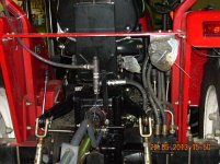
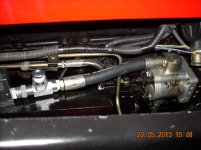
6/15/2015 UPDATE - Repaired Hydraulic Pump Drive.
I decide to repair my current pump and pump drive so that I could keep using the tractor while waiting for new components to arrive. I'll start with a few words about why I think the pump drive failed and then I'll describe how I fixed the driver shaft. I'll discuss the pump shaft fix in a couple of days when it will hopefully be done.
HYDRAULIC PUMP DRIVE FAILURE ANALYSIS
BACKGROUND
The manufacturer of our tractors choose to mate the hydraulic pump to the engine via a drive design that uses a crude universal joint to couple power between the two. This was most likely done so that the tolerances between the pump mount and the drive mount could be rather loose - AKA the pump and drive would be cheaper to manufacture. The only other solution would be to index every hydraulic pump to every drive using dowels. This would also be expensive, and impossible to do for people who purchased their tractor as a kit and are assembling it in a rice patty in some remote village in China. I suppose a better universal joint could also be used - and I think this is what they did in later designs.
The use of a universal joint is in-and-of itself not a bad thing - we use them for all kinds of things every day. It's the nature of this joint design that causes the problem.
This is how the universal joint they used works:
- The input shaft of the pump is round with a flat machined to it's end parallel to the shaft - just like a flat head screw driver.
- The drive shaft (coming from the engine) is also round, with a slot machined into it's end perpendicular to the shaft - just like a flat head screw.
- The flat on the pump shaft is inserted into the slot on the drive - just like we do when we are ready to use a screw driver to drive a screw. In the case of a screw driver and screw torque is applied to the screw driver by our hand (or a motor these days) which then applies that torque to the screw so that it will rotate.
- In the case of our tractors the same coupling is made the flat on then of the pump input shaft is inserted into the slot of the drive shaft. However the reverse of the common screwdriver/screw scenario is true when it comes to the application of torque in the case of our tractors. On the tractor the torque is applied to the drive (slot) which transmits that torque to the input shaft of the pump. If we continue to use our screw driver/screw analogy this would be the equivalent of the screw driving the screw driver - AKA backwards from what we normally experience.
GOOD ASPECTS OF THIS DESIGN
Everyone that has ever driven a screw knows that a mismatch of screwdriver size versus screw slot size and slight misalignment of the screwdriver and screw does not cause much trouble - usually that is.
PROBLEMS WITH THIS DESIGN
But what happens if the screw is over torqued?? - EXACTLY we usually strip the slot in the screw. And what happens when the slot strips? It doesn't sheer off, if usually forms ramps that cause the screw driver to ride up and out of the slot instead of turning the screw.
EARLY WARNING SIGNS
Unfortunately I missed the following early warning signs and self inflicted causes: Hopefully you won't!
- A week prior this latest failure the pump had also broken loose from it's drive with very little damage resulting. I assumed a fatigued bolt was the cause and put it all back together with two new bolts. Thank GOD I was unable to locate grade eight metric bolts!
- Two weeks prior the high pressure hose from the pump outlet to the QD exploded. I assumed it was due to fatigue of the hose and replaced it. I did at least bypass the QD, but only for lack of a proper fitting - not becuase I knew they were a potential cause. In any event a deadhead situation occurred again so it if was a QD problem it must have been the other one which I left on.
- A year prior I disconnected the FEL and didn't know that the QD's still on the tractor needed to be connected to each other. The engine stalled twice before I consulted this forum and realized my major F&*ck-up. The pump was never the same after this. Probably due to internal damage to the seals that has resulted in a partial internal bypass.
FAILURE SYMPTOMS
In the case of my failure the exact same thing happened as described in our analogy: too much torque was applied - the slot in the drive striped - and the pump shaft was driven up and out of the slot. When the pump was driven away from the drive the bolts holding the two together snapped and the drive was then free to turn and the pump was free to stay locked.
ROOT CAUSE
I imagine that the amount of torque and counter torque required to strip the drive slot must be significant and that barring a screwdriver falling into the pump's input that it must have been some other cause of a complete pump lockup. In my case I suspect that the pump locked up (infinite counter torque) as a result of a "deadhead" condition; becuase of course a liquid cannot be compressed. However I can't tell for sure, and I never found a definitive cause for the deadhead in this particular case.
CORRECTIVE ACTIONS
As many have advised me, the way to prevent all of this nastiness is to never deadhead the pump. Of course that's not always foolproof when you are old and absent minded as me. The back-up plan that many on this board have implemented (and that I now intend to implement) is to relieve the pressure from a pump when it climbs high enough to either blow seals, split the case or produce so much counter torque on the pump input shaft as to strip the slot of the drive shaft, or sheer either or both shafts entirely.
REMAINING ISSUES
Even with the above solution (pressure relief valve) I don't like this coupling design because it allows the pump drive to move in the slot thereby causing wear over time and weakening the metal where they two contact each other; to the point that much less torque is required to strip the drive.
CREDITS
My wife took all the pictures. Thanks Love.
99% of the info here comes from other smart people on this and other forums that helped me and or shared their experience and fixes with the world.
Affordable Tractor Sales supplied one of the pictures in the next section.
NOTES: FOR THOSE SUSPECTING OR SEEING SIMILAR PROBLEMS
Others have seen different failure symptoms, but that they also attribute to a pump lockup. I recall reading about these other symptoms that people have seem in their posts:
- The pump housing splits open
- A hose ruptures
- The seals internal to the pump blow out and the pump then internally bypasses itself - AKA dead hydraulics - no apparent problem
- The front seal on the hydraulic pump blows out. Leaking/spraying fluid then enters the engine via the pump drive and timing cover. Cannot be detected and can/will damage engine!!!
- The FEL valves blow apart if the blockage is downstream from them
Many of these people believe that their a pump lockup/over-pressure was due to following possible causes:
- Faulty quick disconnects(QD's)
- Forgetting to cross couple the QD after the FEL is taken off (I have done this myself)
- QD that have fully or partially disconnected themselves. Happens when the collars slide/are bumped back, etc.
Regardless of the cause the situation resolves itself (most often destructively) when counter torque from the hydraulic pump to the drive is released - either becuase hydraulic fluid found a way out upstream from the deadhead cause, the drive sheared (my case), or if you are lucky the engine stalled.
READ OTHER PEOPLE's POSTS ABOUT THIS PROBLEM. THEY PROVIDE EXCELLENT INFO ON PREVENTION AND OTHER POSSIBLE CAUSES.
PUMP DRIVE FIX/PATCH"
I decided to fix my unit becuase I wanted to order a new pump and drive with other items that I am not yet ready to order AND becuase I needed the tractor this last Sunday.
I decided to use my Tig welder to add metal to the part where it needed it.
Yes - I did weld the shaft while it was still pressed into the bearings. I did this becuase there was no way to press the shaft free of the bearings without damaging the bearings. Since I had no source for new bearings on Sunday - and becuase the whole objective was to have the tractor up and running by Sunday I went ahead and welded the shaft as it was.
To minimize the chance of potential damage to the bearings I would only weld until the oil in the bearings started to smoke and then I would back off and let the whole thing cool down. I have no idea if the bearings were saved from damaged as a result of this procedure. Ill inspect them in a few hours and see. Long term I'll buy a new drive gear and pump anyway.
One of the pictures shows where I had to grind away metal after my first pass of weld. This was done to remove a bunch of voids that were created when bubbles formed in the molten metal during welding. I believe those bubbles were the result of some contaminant. I checked all possible sources of external contamination but couldn't find any. I concluded that there was some kind of impurity in the cast steel which had a vapor temperature very close to the melting point of the steel and welding rod. At this point I should have decided to braze the part - BUT I DIDN'T. Instead I decided to regulate the heat applied to just enough required so that drive and rod would melt and fuse. The trick was not applying any more heat otherwise the , the contaminate would vaporize and form the bubbles/voids. It mostly worked.
After the metal was put back I cleaned up the face in the lathe and re-cut the slot using an ancient milling attachment for the lathe.
Finally I cleaned it for what seamed forever in order to make sure that all the metal shavings, grinding dust and cats and dogs were out of it. I then lubed it up and put it back on the timing cover.
I'll show the fix to the pump shaft in a couple of days when it's done
I HOPE ALL THIS HELPS THE NEXT GUY AS MUCH AS EVERYONE HELPED ME GET TO THE BOTTOM OF THIS ISSUE.
Drive Gear(female) before repair. It looks just like a stripped screw does't it?
Here is what the drive is supposed to look like. Photo credit to Affordable Tractor Sales - buy a new one from them if you don't want to fix yours! They are very supportive of this forum and offer lots of free advice.
Here is a picture of the drive all cleaned up and ready to be welded.
The voids discussed above have been ground out of the part after my first attempt to weld to it. I have less metal in the part now than when I started!
All Done. Lets see how it holds up over time???


