OP
dfkrug
Super Member
- Joined
- Feb 3, 2004
- Messages
- 7,674
- Location
- Santa Cruz Mtns, CA
- Tractor
- 05 Kioti CK30HST w/ Prairie Dog backhoe, XN08 mini-X
OK, now a few calculations for those who might wonder.
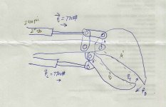
The goal here is to make a thumb that does not over-power the bucket, and vice versa. I have scribbled up a drawing to help illustrate my design.
Each cylinder is 2" (50mm) ID, and the pump puts out about 2400psi. This yields a pushing force of about 7700psi, maximum. The bucket cylinder pushes about the bkt pivot, with moment arm, A. The thumb pushes about the thumb pivot, with moment arm, B.
After sizing the cylinders (both 2" ID), the second major design parameter is to make A and B the same length. Unfortunately, the geometry of the thumb forced me to go with a somewhat larger B, in order for the thumb to swing fully out of the way. So, I ended up with A at 3.5", and B at 5". A' is the length of the bucket, from pivot to tip (15"), and B' is the length of the thumb, from pivot to tip (17").
The forces on the bkt or thumb vary widely, depending on the angle of the moment arm, and the pressure point of the load on the bkt and thumb. For simplification, I will look at the forces on the tips of each, when the moment arms are each at their positions where maximum forces are applied. These are the vectors, F(T) and F(B) in the drawing. The ratios of moment arm to element length are: A/A' = .23 for the bkt, and B/B' = .29 for the thumb. This means that the magnitude of F(T) = .29 x 7700 = 2270#. For the bucket, F(B) = .23 x 7700 = 1800#
The thumb can push harder than the bucket, but is that a problem?
If the thumb pushes on the bkt with 2270#, the resulting force on the bkt cylinder will be 2270/.23 = 9870#. 9870/piRsqd = 3140psi. Given the construction of these cylinders, I am comfortable with that pressure, without using a work-port relief valve or crossover RV.