Making Lift Arm Telescoping sway bars

   / Making Lift Arm Telescoping sway bars
  • Thread Starter
#11  
John, Rob thanks for the comments.

I sort of plan on laying out some holes after putting this on the tractor...BUT..

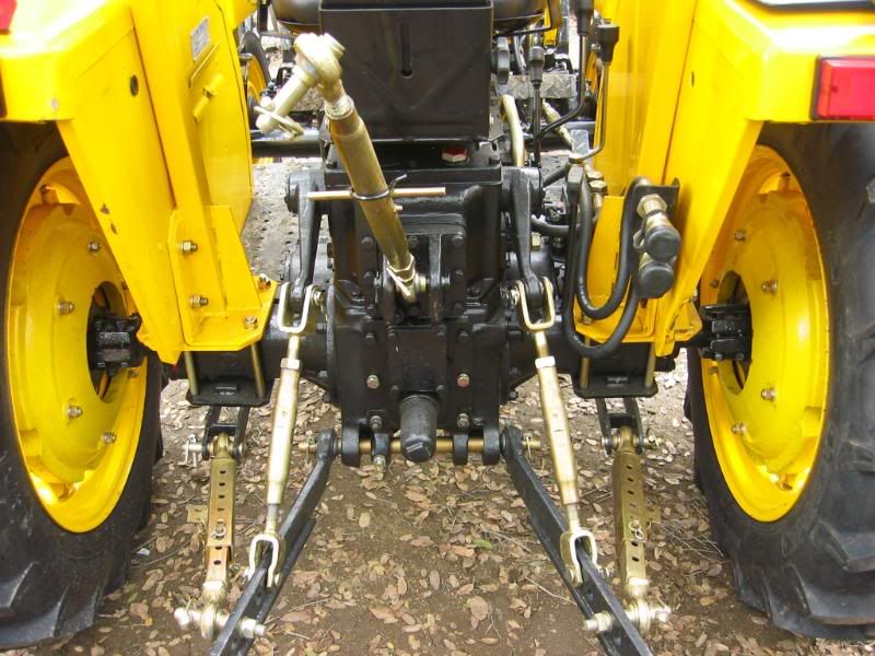
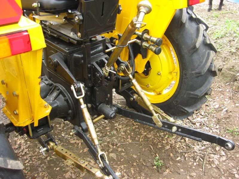
I'm not sure on the slot thing, just how much movement is needed? The slot on the factory ones looks like a couple inches. Seems like a lot of movement. I'm really not sure how to start noodling that part of project. Just mimic the OEM set up and let of go?

Regarding the U joints, the other night I bent some more of the 3/8 flat bar. I think I'm going to do the other side with that and see how it comes out. Generally I'm making things in pairs while I have everything out.

BTW no work yesterday, out of town. Then my sone comes in from college for spring break today. I'll get some time tomorrow, hey we may get some snow today!!


Thanks,
Rob
 
   / Making Lift Arm Telescoping sway bars #12  
The slot is very helpful. not only when you use the slots on both sides to let implements "roam". But also when you pin one side tight and slot the other while picking up at odd angles, rusted pins, kicked as hard as you can and still wont line up, I use it quite a bit. Also weld a little pin holder, even though mine have chains to keep the pins close, I never leave them dangling, I always put them in a hole or in the holder, wich is just a little L bracket welded to the outside of the swaybars. As for a pin a T or an L is all you need, drop in from top no clips or retainers on the bottom and I have never had one pop out, even in rough use in the bushes.
 
   / Making Lift Arm Telescoping sway bars
  • Thread Starter
#13  
It is finished.....

I removed the lighter 1/4" steel U joint and used the thicker 3/8" steel. So I have a spare set of those now. I was going to wait and drill the holes after the first install but had the time. Spaced the ones on the outside about 1.25", ones on the inside bar about 3/4". I'll figure out the slot later. I have a couple implements with odd widths so I may want to find some way to make all of them the same so I won't have to fuss with it all the time.

Hardest part this weekend was getting the holes to line up. I just clamped on a guide to my drill press. One hole slipped off when some shaving got behind it. All others are ok. Picked up the 3/8 pin to secure the, I drilled the hole one drill bit larger than 3/8...just in case. :D

BTW that red drill index came from HF, $9.95 for the set. It's a real good set. Been drilling all the metal from that set on this project. HEck of a deal for that price. I actually picked up 2 more sets at HF sidewalk sale this weekend.

NExt pic...on the tractor! I still have to weld everything solid. I might do that this week because all indications seems to point to it fitting ok.

Rob
 

Attachments

  • 03082008.JPG
    03082008.JPG
    114.2 KB · Views: 637
  • 03082008 (1).JPG
    03082008 (1).JPG
    124 KB · Views: 533
  • 03082008 (2).JPG
    03082008 (2).JPG
    146.8 KB · Views: 562
   / Making Lift Arm Telescoping sway bars
  • Thread Starter
#14  
3RRL said:
Rob,
By the looks of things, your drag links could've used them before now?:)

Hey Rob, by drag links you mean the lift arms? The right lift arm has suffered the same fate as some others here at TBN. Bent! Bent like it was trying to pick up to much weight, bent right where it attaches on the link. It was also bent a little to the outside. I took a 16# sledge one day and gave it a little correction. You can't really tell, a new arm is about $135 if I recall.

Rob
 
   / Making Lift Arm Telescoping sway bars #15  
RobJ said:
Hey Rob, by drag links you mean the lift arms? The right lift arm has suffered the same fate as some others here at TBN. Bent! Bent like it was trying to pick up to much weight, bent right where it attaches on the link. It was also bent a little to the outside. I took a 16# sledge one day and gave it a little correction. You can't really tell, a new arm is about $135 if I recall.

Rob
Yeah, that's what I mean ... lower lift arm or lower drag link (the links used to drag your implements). Depends where you're from I guess. I bent mine too but from bull dozing in reverse. Mine are about 1" thick by 4" tall too, and I add a 3/4" thick x 3" tall bar over the length of the drag ink, so it now forms an upside down "T".

It's funny, after first reading your thread a couple weeks ago, I just broke off my stabilizer bar...dang. I fixed it already, but mine are round and I really like your square ones. I was also thinking, if you have enough slop in those "U" joints, where there is some movement, maybe that could take the place of the slot? Otherwise just machine that last drilled hole on the outer tube (nearest the "U" joint) to be a 1" or so long slot. That would give you the opportunity to pin the 2 sliding pieces together using that slot when needed, or without using the slot by pinning in another set of holes.
But regardless, they look really good man!
 
   / Making Lift Arm Telescoping sway bars #16  
RobJ said:
I removed the lighter 1/4" steel U joint and used the thicker 3/8" steel.
I've never liked those U-joints. My tractor has a set just like them also. If the stabilizers aren't tight enough, they let the u-joints flop around. I just finished a replacement for them. I haven't been able to install them yet.
PhotoLink
 
   / Making Lift Arm Telescoping sway bars
  • Thread Starter
#17  
3RRL said:
Yeah, that's what I mean ... lower lift arm or lower drag link (the links used to drag your implements). Depends where you're from I guess. I bent mine too but from bull dozing in reverse. Mine are about 1" thick by 4" tall too, and I add a 3/4" thick x 3" tall bar over the length of the drag ink, so it now forms an upside down "T".

It's funny, after first reading your thread a couple weeks ago, I just broke off my stabilizer bar...dang. I fixed it already, but mine are round and I really like your square ones. I was also thinking, if you have enough slop in those "U" joints, where there is some movement, maybe that could take the place of the slot? Otherwise just machine that last drilled hole on the outer tube (nearest the "U" joint) to be a 1" or so long slot. That would give you the opportunity to pin the 2 sliding pieces together using that slot when needed, or without using the slot by pinning in another set of holes.
But regardless, they look really good man!

OK so where's my pic of this setup?? :D I've thought about welding on some extra support but would probably replace the link first. Mine are 3/4", maybe 5/8" thick and I believe about 3" tall. Maybe 2 3/4". I've never put the tape on them.

Just a little play in the U joints, I tighten them up as much as possible. I even welded a couple beads on the tip of the ROPS bracket to tighten them up. We'll see how it works. I like the idea of locking the arms in place when nothing is attached. Mine will swing out and hit the tire.
 
   / Making Lift Arm Telescoping sway bars
  • Thread Starter
#18  
JerryG said:
I've never liked those U-joints. My tractor has a set just like them also. If the stabilizers aren't tight enough, they let the u-joints flop around. I just finished a replacement for them. I haven't been able to install them yet.

Hey Jerry you have to post some pics of that set up. I like the idea. I don't have enoough room on mine to hook one of those up without some more fab work. There are 2 holes on the bottom of the rops bracket (always wonder why stuff like this is there or what its intended for) to come off with for a bracket. They would hang down a bit. Pics would be great when you are done!

Rob
 
   / Making Lift Arm Telescoping sway bars #19  
RobJ said:
OK so where's my pic of this setup?? :D I've thought about welding on some extra support but would probably replace the link first. Mine are 3/4", maybe 5/8" thick and I believe about 3" tall. Maybe 2 3/4". I've never put the tape on them.
You've probably seen these before? I have a spare drag link but opted to straighten the bent ones and weld the support "T" to them. I used a ripper shank (scarifier) from my boxblade as the "T" welded to the bottom. (I'm a cheapskate). Notice the welds are pretty heavy duty.
You can also see my stabilizers next to the drag links. They are 3 piece construction. They have holes like yours and a slot which you can see best in the first picture.


I don't know if you can see it or not, but the drag links on my wife's Jinma came stock with the "T" welded on the bottom. I thought that was pretty interesting.

 
   / Making Lift Arm Telescoping sway bars
  • Thread Starter
#20  
Now I could have used those sooner!! :) Actually I saw the thread of the new Jima but didn't recall that in the pics.

Couple things that stand out, not surprised the lift arms have some added support, they look a little skinnish, maybe just the picture effect. But I do like the sway bar set up. Definately what JErry is going for I think. I'd have to weld another plate on the other side of my rops plate to get the proper support for the pin. Some type of shackel set up. But this is a nice set up with the swivels. Now the outside square tubing doesn't look to heavy either. How thick is that? Also can't tell if the inside piece is solid or not. Am I missing seeing a slot or is the washer covering that.

Good pics man!! Looks like I'm in for another redesign later this year!! But that's the fun part.

Rob
 

Tractor & Equipment Auctions

2003 Big Tex 10PI 16ft. T/A Pipe Top Utility Trailer (A49461)
2003 Big Tex 10PI...
PAIR OF 29 FT PIPE RACKS (A50854)
PAIR OF 29 FT PIPE...
2020 CATERPILLAR 938M WHEEL LOADER (A51242)
2020 CATERPILLAR...
2012 Infiniti G25 (A50324)
2012 Infiniti G25...
3014 (A50657)
3014 (A50657)
72in Rock Bucket Skid Steer Attachment (A50322)
72in Rock Bucket...
 
Top