hwp
Platinum Member
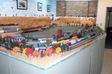
I dabble in model railroading and I currently have two engines that have the same problem (same manufacturer, same wheel configuration [4-8-4], different road names), the drive wheels are loose from the drive axle. This is a common problem with these models. These are fairly good quality older plastic models, admittedly not brass, but worth restoring. To put this in perspective, I would be willing to pay up to $100 per engine to have them fixed properly.
The models work in a similar way as the prototypes, with one major difference. The real ones were driven by steam pistons whereas the models have electric motors. On both, power is initially transfered to one axle and then side irons are used to transmit power to the other drive whels on the same side of the engine. In order to have a reasonably smooth running locomotive, the driving wheels have to be quartered, meaning that the drive wheels have to be oriented so that the dowels for connecting the side irons are exactly ninety degrees apart from each other. In the models there is a drive gear in the middle of the axle between the two drive wheels. All driver axles are rigid, so power applied to a drive wheel on one side also provides power to the other drive wheel on that axle. As a result the axles are always getting power from one side or the other. So you end up with a sequence such as: push left, push right, pull left, pull right. This only works if the drive wheels properly quartered, otherwise the mechanism works against itself.
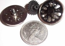
I have tried gluing the drivers to the axles with ACC but that didn't work, possibly due to faulty quartering on my part. I also tried making a flat spot on the axle before gluing but that didn't work either, possibly for the same reason. My current thoughts are to cross drill the hubs and axles and insert pins though the hubs and axles to have positive connections. between the hubs and the axles. The question is whether or not this is viable. The axles are 2mm (0.078") in diameter. I am thinking of using 1mm (0.039") cross pins. Can this be done on a micro lathe? Or is there a better type of machine for doing this? Drilling the 1mm holes though the hubs and axles shouldn't be too hard with the proper equipment, but obviously it can't be done by hand, at least not by me. But what about the indexing to ensure that the drivers are properly quartered? There are quartering marks scribed on the inside surfaces of the drive wheels. Any thoughts on how I might find someone who could do this for me? Thanks. /forums/images/graemlins/smile.gif
The models work in a similar way as the prototypes, with one major difference. The real ones were driven by steam pistons whereas the models have electric motors. On both, power is initially transfered to one axle and then side irons are used to transmit power to the other drive whels on the same side of the engine. In order to have a reasonably smooth running locomotive, the driving wheels have to be quartered, meaning that the drive wheels have to be oriented so that the dowels for connecting the side irons are exactly ninety degrees apart from each other. In the models there is a drive gear in the middle of the axle between the two drive wheels. All driver axles are rigid, so power applied to a drive wheel on one side also provides power to the other drive wheel on that axle. As a result the axles are always getting power from one side or the other. So you end up with a sequence such as: push left, push right, pull left, pull right. This only works if the drive wheels properly quartered, otherwise the mechanism works against itself.
I have tried gluing the drivers to the axles with ACC but that didn't work, possibly due to faulty quartering on my part. I also tried making a flat spot on the axle before gluing but that didn't work either, possibly for the same reason. My current thoughts are to cross drill the hubs and axles and insert pins though the hubs and axles to have positive connections. between the hubs and the axles. The question is whether or not this is viable. The axles are 2mm (0.078") in diameter. I am thinking of using 1mm (0.039") cross pins. Can this be done on a micro lathe? Or is there a better type of machine for doing this? Drilling the 1mm holes though the hubs and axles shouldn't be too hard with the proper equipment, but obviously it can't be done by hand, at least not by me. But what about the indexing to ensure that the drivers are properly quartered? There are quartering marks scribed on the inside surfaces of the drive wheels. Any thoughts on how I might find someone who could do this for me? Thanks. /forums/images/graemlins/smile.gif